00196504-02_UM_X-Serie_SR70X_EN.pdf - 第266页
Setting up and commissioning User manual SIPLACE X-series Setting up the machine From software version SR.70x.xx 01/2011 EN edition 266 4.3.13 Inst alling the axis unit 4.3.13.1 Axis unit X4I, X4, X3 (gantry 1 and gantry…

User manual SIPLACE X-series Setting up and commissioning
From software version SR.70x.xx 01/2011 EN edition Setting up the machine
265
4.3.12.3 Box PC unit for SIPLACE X4I - connecting the plugs on the rear panel
4
4
4.3.12.4 Installing the box PC unit on the SIPLACE X4I
→ Connect the yellow-green grounding cable to the box PC unit, as shown in Fig. 4.3 - 16, page
257
.
→ Plug in the plug-in connectors on the rear panel of the box PC unit (see Section 4.3.12.3
,
page ).
→ Carefully lift the box PC unit onto the rail in the extension kit.
→ Make sure that you do not squash any cables.
→ Push the box PC unit into the extension kit as far as the stop.
→ Plug in the plug-in connectors on the front panel of the box PC unit (see Section 4.3.12.2
,
page 264
).
→ Fix the cables to the front panel with cable ties.
→ Secure the box PC unit with the fillister head screw.
→ Fix the grounding cable to the doors (item 2 in Fig. 4.3 - 15
, page 254),
as shown in Fig. 4.3 - 16
on page 257.
→ Lock the doors.
Box PC unit
(Fig. 4.3 - 20
, page 263)
plugs
Connecting cable Please note:
the plugs can be accessed
from the rear panel
Plug Cable
X3rz X3rz 03050907 Insert as far as the stop
X10rz X10rz 03056891 Insert as far as the stop
Setting up and commissioning User manual SIPLACE X-series
Setting up the machine From software version SR.70x.xx 01/2011 EN edition
266
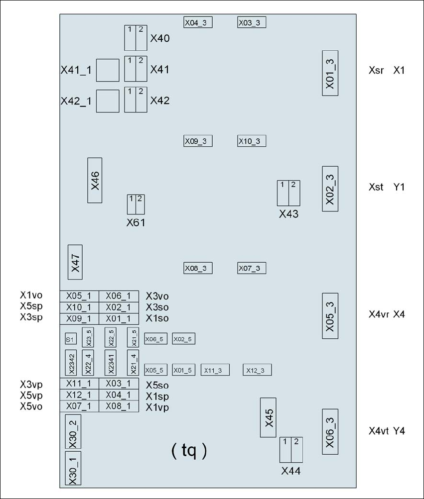
4.3.13 Installing the axis unit
4.3.13.1 Axis unit X4I, X4, X3 (gantry 1 and gantry 4) - electrical connection points
4
Fig. 4.3 - 21 Axis unit X4I, X4, X3 (gantry 1 and gantry 4), rear panel - connecting the plugs
Plug
Plug
Plug

User manual SIPLACE X-series Setting up and commissioning
From software version SR.70x.xx 01/2011 EN edition Setting up the machine
267
4.3.13.2 Axis unit X4I, X4. X3 (gantry 1 and gantry 4) - Connecting the plugs
→ Connect the power cable as shown in the following diagram:
4
Axis unit, plugs Connecting cable Please note
Plug Cable
X41_1tq X41_1tq 03050919 Snap connector into place
X42_1tq X42_1tq 03050919 Snap connector into place
X45tq X45tq 03050920-W1 Snap connector into place
X46tq X46tq
03050920-W2
03050920-W3
Snap connector into place
X47tq X47tq
03050920-W4
03050920-W5
Snap connector into place
X01_3tq X4sr 03050881 Snap connector into place
X02_3tq X4st 03050882 Snap connector into place
X05_3tq X4vr 03050911 Snap connector into place
X06_3tq X4vt 03050912 Snap connector into place
X01_1tq X1so 03009771 Insert as far as the stop
X02_1tq X3so 03009772 Insert as far as the stop
X03_1tq X5so 03009773 Insert as far as the stop
X04_1tq X1sp 03009774 Insert as far as the stop
X05_1tq X1vo 03009831 Insert as far as the stop
X06_1tq X3vo 03009832 Insert as far as the stop
X07_1tq X5vo 03009833 Insert as far as the stop
X08_1tq X1vp 03009834 Insert as far as the stop
X09_1tq X3sp 03009775 Insert as far as the stop
X10_1tq X5sp 03009776 Insert as far as the stop
X11_1tq X3vp 03009835 Insert as far as the stop
X12_1tq X5vp 03009836 Insert as far as the stop
X03_3tq X03_3tq 03050883 Snap connector into place
X04_3tq X04_3tq 03050884 Snap connector into place
X07_3tq X07_3tq 03050913 Snap connector into place
X08_3tq X08_3tq 03050914 Snap connector into place