00196504-02_UM_X-Serie_SR70X_EN.pdf - 第221页
User manual SIPLACE X-series Setting up and commissioning From software version SR.70x.xx 01/2011 EN edition Infrastructure at the installation location 221 4.2.3.1 Danger notes W ARNING The machine is supplied with 3 x …
Setting up and commissioning User manual SIPLACE X-series
Infrastructure at the installation location From software version SR.70x.xx 01/2011 EN edition
220
4.2.3 Main power supply
4
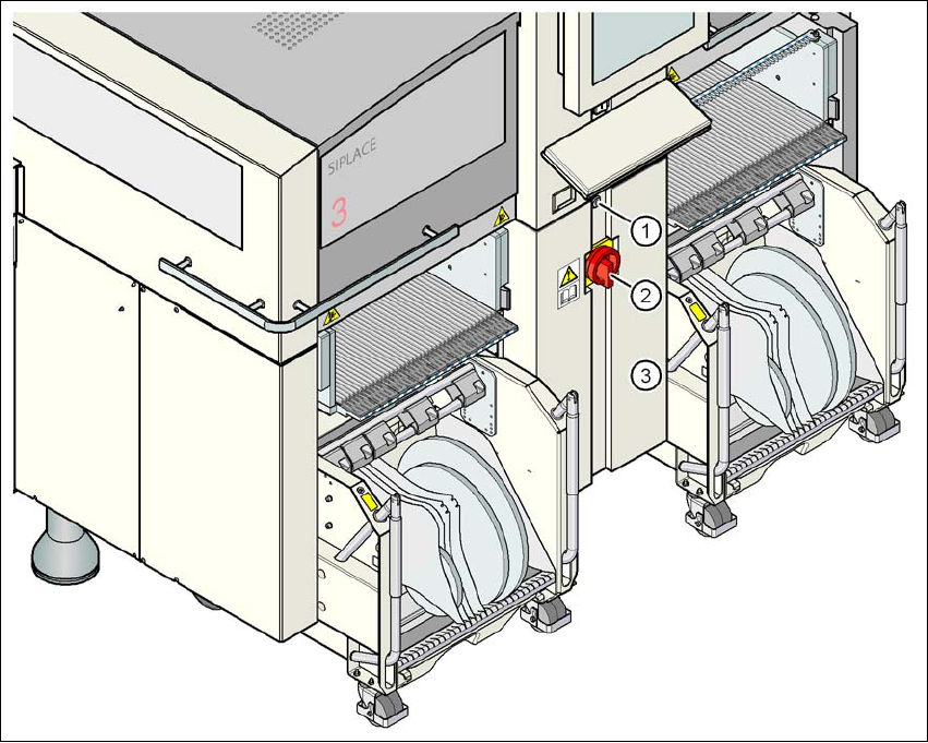
Fig. 4.2 - 2 Position of the power supply on the machine
4
(1) Lock
(2) Main power switch secured to prevent switching on again
(3) Cover
User manual SIPLACE X-series Setting up and commissioning
From software version SR.70x.xx 01/2011 EN edition Infrastructure at the installation location
221
4.2.3.1 Danger notes
WARNING
The machine is supplied with 3 x 200 VAC, 3 x 208 VAC, 3 x 230 VAC, 3 x 380 VAC,
3 x 400 VAC or 3 x 415 VAC ± 5 %, 50/60 Hz mains voltage. This means that some parts of the
system carry potentially lethal voltages - even when switched off at the main power switch. In-
correct handling of the machine can therefore result in death or severe injury or considerable
damage to equipment. 4
→ Always follow the applicable accident prevention and DIN regulations (particularly DIN EN 60
204, part 1).
→ Only trained and qualified personnel may remove the cover over the power supply unit and
connect the machine to the power supply.
4
4
4.2.3.2 Checking the main power supply
Check that the main power supply conforms to the prescribed machine specifications (see table
in Section 3.2
, page 105).
PLEASE NOTE: 4
The document entitled "Network configuration (electrical and compressed air) for SMD systems
on the customer's premises", item no. 00191409-xx, describes the action that can be taken to
meet the required specifications.
PLEASE NOTE: 4
For technical reasons, load peaks occur in the power supply. Please contact your power com-
pany to clarify the mains impedance, if necessary.
4.2.3.3 Power supply cable - specification
The following specifications apply to the power supply cable:
5 x 6 mm² for 3 x 380 VAC / 3 x 400 VAC / 3 x 415 VAC
5 x 6 mm² for 3 x 200 VAC / 3 x 208 VAC / 3 x 230 VAC
The color coding for the wires will depend on the country in which the system is operated.
Setting up and commissioning User manual SIPLACE X-series
Infrastructure at the installation location From software version SR.70x.xx 01/2011 EN edition
222
WARNING 4
The electrical cables to each individual machine and to the installed options (e.g. MTC) must be
clearly identified and there must be no doubt as to their allocation. The regulations of the country
in which the machine is operated apply.
4
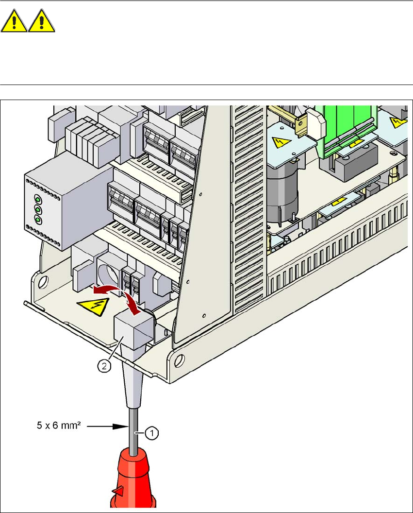
Fig. 4.2 - 3 Cross-section of the main power cable
(1) Power supply cable
(2) Angle for the cable gland