00196504-02_UM_X-Serie_SR70X_EN.pdf - 第327页
User manual SIPLACE X-series Tasks on the machine From software version SR.70x.xx 01/2011 EN edition Setting up the feeder modules 327 5.10 Setting up the feeder modules 5.10.1 Notes on handling feeder modules Feeder mod…
Tasks on the machine User manual SIPLACE X-series
Carrying out a walk-through inspection From software version SR.70x.xx 01/2011 EN edition
326
5.9.5 Inserting separating plates in the tape container
→ The separating plate has different edges and can be inserted into the tape container in two
ways. If quick-release axles are used, the recesses for the quick-release axles in the sepa-
rating plate point upwards (see item 4 in Fig. 5.9 - 3
). If you do not use quick-release axles,
the rounded edge of the separating plate points up (see item 5 in Fig. 5.9 - 3
).
→ Insert the separating plates as shown in Fig. 5.9 - 3
and remember that the smallest division
of the tape container is a 2x division. This will help avoid placement errors.
→ Check that the separating plates engage in the same positions on the three guide rails. Oth-
erwise the separating plate will be offset or bent.
5
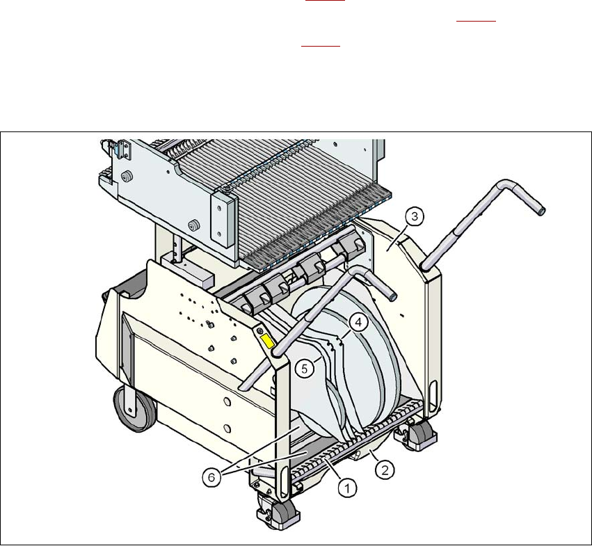
Fig. 5.9 - 3 Separating plates in the tape container
(1) Guide rail for the separating plates
(2) Waste tape container
(3) Tape container
(4) Position of the separating plate if quick-release axles are used
(5) Position of the separating plate if no quick-release axles are used
(6) Slide surfaces for the tape reels
User manual SIPLACE X-series Tasks on the machine
From software version SR.70x.xx 01/2011 EN edition Setting up the feeder modules
327
5.10 Setting up the feeder modules
5.10.1 Notes on handling feeder modules
Feeder modules are precision devices. You should therefore handle the feeder modules with care.
→ Avoid bumping feeder modules into obstacles.
→ Do not drop the feeder modules.
→ Always use suitable tools for preventive maintenance.
5.10.2 Removing X feeder modules from the component table
5
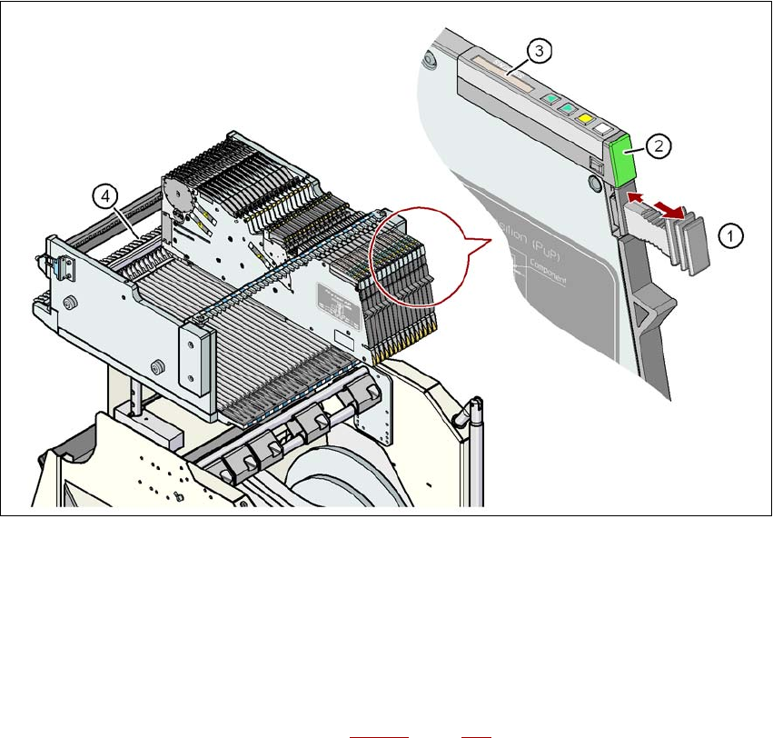
Fig. 5.10 - 1 Removing X feeder modules from the component table
(1) Removal handle
(2) Status display
(3) LCD display
(4) Latch for locking the X feeder modules
5
On standby, the status display (item 2 in Fig. 5.10 - 1, page 327) lights up green if the X-axis feeder
module is contained in the current set-up. If the feeder module is not contained in the current set-
up, the status display remains off.
Tasks on the machine User manual SIPLACE X-series
Setting up the feeder modules From software version SR.70x.xx 01/2011 EN edition
328
The X feeder module is locked in position in the component table by a latch, and cannot be pulled
out. The procedure for removing feeder modules from the component table is as follows:
→ Press the removal handle (item 1 in Fig. 5.10 - 1
, page 327). The removal handle jumps
out and the status display goes out.
→ Wait approximately 1 second until the lock (item 4 in Fig. 5.10 - 1
, page 327) releases
the feeder module.
→ Use the removal handle to pull the feeder module out of the component table. If you wait
longer than 5 seconds, the feeder module will be locked once more. The status display
lights up red and the message "Handle --->>" appears on the LCD display (item 3 in Fig.
5.10 - 1
, page 327).
→ Engage the removal handle once more. If the X feeder module is contained in the current
set-up, the status display lights up green and the track number and increment are appear
on the LCD display once more.
→ Press the removal handle again (item 1 in Fig. 5.10 - 1
, page 327) and now pull the feeder
module out of the component table.
5.10.3 Using the X feeder module on the component trolley
5.10.3.1 Check the X feeder module before using it
Check the following points before you use a feeder module on the component table:
→ The feeder module must be in perfect condition.
→ Tap the cover foil rocker (item 2 in Fig. 5.10 - 2
, page 329) lightly to make sure that it is
not jammed.
→ Check that the area around the pick-up window (item 3 in Fig. 5.10 - 2
, page 329) is free
from loose components.
PLEASE NOTE 5
Empty the component disposal compartment (item 5 in Fig.5.10 - 2
, page 329) before you
shake components out of the feeder module.
→ Push the lever (item 4 in Fig. 5.10 - 2
, page 329) forward slightly to open the pick-up win-
dow (item 3 in Fig. 5.10 - 2
, page 329). This will raise the pick-up window slightly.
PLEASE NOTE 5
Do not press the lever if a component tape is inserted. The tensioned cover foil would move
the component tape on and expose the components.
→ Remove any loose components from beneath the pick-up window.