00196504-02_UM_X-Serie_SR70X_EN.pdf - 第219页
User manual SIPLACE X-series Setting up and commissioning From software version SR.70x.xx 01/2011 EN edition Infrastructure at the installation location 219 4.2.2.2 Compressed air connection on the machine 4 Fig. 4.2 - 1…
Setting up and commissioning User manual SIPLACE X-series
Infrastructure at the installation location From software version SR.70x.xx 01/2011 EN edition
218
4.2.1.2 Vibration limits
The machine is not sensitive to ground vibration, but the following vibration limits should still be
observed.
4
4
4
4
4
4.2.2 Compressed air supply
4.2.2.1 Checking the compressed air supply
Check that the compressed air supply conforms to the prescribed machine specifications (see ta-
ble in Section 3.2
, page 105).
PLEASE NOTE: 4
The document entitled "Network configuration (electrical and compressed air) for SMD systems
on the customer's premises", item no. 00191409-xx, describes the action that can be taken to
meet the required specifications.
→ Record the compressed air characteristics at the installation location.
WARNING
NEVER detach compressed air lines while they are still pressurized. Risk of injury. 4
Parameters Values
Third-octave spectral value of the vibration speed 5 - 100 Hz
v < 250 µm/s
v
max
value on the time curve
v
max
< 1.5 mm/s
User manual SIPLACE X-series Setting up and commissioning
From software version SR.70x.xx 01/2011 EN edition Infrastructure at the installation location
219
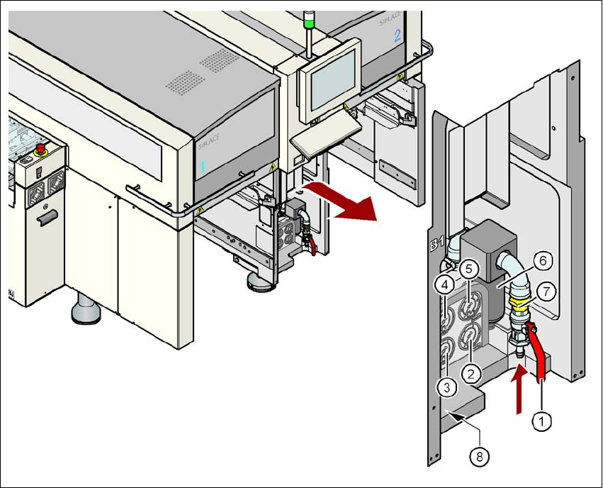
4.2.2.2 Compressed air connection on the machine
4
Fig. 4.2 - 1 Compressed air line connection
(1) Stop valve in the "OPEN" position
(2) Manometer for the machine component supply pressure
Desired pressure: 0.5 ± 0.025 MPa, 5 ± 0.25 bar (display range 0 - 0.6 MPa, 0 - 6 bar)
(3) Manometer for the gantry distributor supply pressure
Desired pressure: 0.46 ± 0.01 MPa, 4.6 ± 0.1 bar (display range 0 - 0.6 MPa, 0 - 6 bar)
(4) Manometer for the bulk case feeder modules supply pressure
Desired pressure: 0.25 ± 0.05 MPa, 2.5 ± 0.5 bar (display range 0 - 0.6 MPa, 0 - 6 bar)
(5) Manometer for the input pressure
Desired pressure: 0.5 - 1.0 MPa, 5 - 10 bar (display range: 0 - 1.0 MPa, 0 - 10 bar)
(6) Compressed air filter
(7) Compressed air connection
(8) Hexagon socket head screw for fixing the pneumatic unit
Setting up and commissioning User manual SIPLACE X-series
Infrastructure at the installation location From software version SR.70x.xx 01/2011 EN edition
220
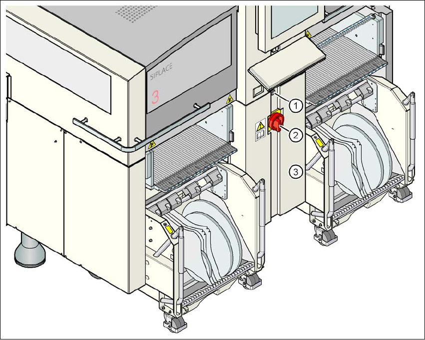
4.2.3 Main power supply
4
Fig. 4.2 - 2 Position of the power supply on the machine
4
(1) Lock
(2) Main power switch secured to prevent switching on again
(3) Cover