00196504-02_UM_X-Serie_SR70X_EN.pdf - 第227页
User manual SIPLACE X-series Setting up and commissioning From software version SR.70x.xx 01/2011 EN edition Setting up the machine 227 4.3 Setting up the machine 4.3.1 PCB conveyor he ight on the machine The machine can…
Setting up and commissioning User manual SIPLACE X-series
Infrastructure at the installation location From software version SR.70x.xx 01/2011 EN edition
226
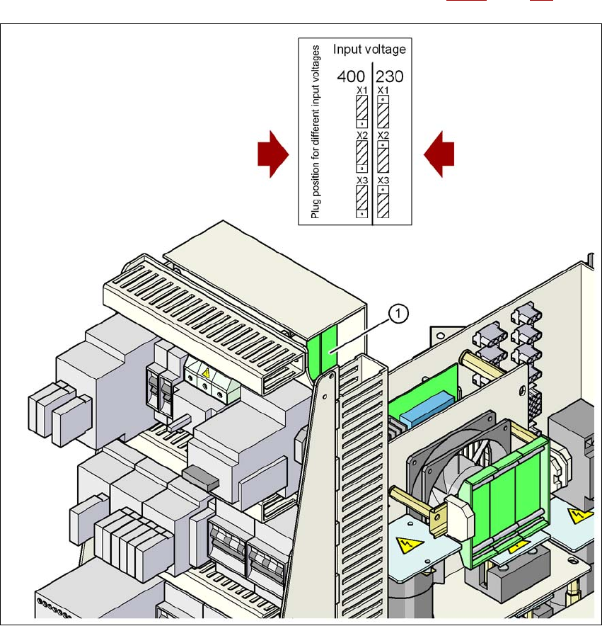
4.2.3.6 Checking the inrush current limitation jumpers
The inrush current limitation must be configured in relation to the supply voltage. This is done us-
ing plug-in jumpers on the inrush current limitation board (item 1 in Fig. 4.2 - 7
, page 226).
4
Fig. 4.2 - 7 Position of the board and connectors for the inrush current limitation
4
(1) Inrush current limitation board
X1, X2, X3 Connectors for configuring the inrush current limitation on the board
→ Check the jumper assignment and correct if necessary.
3 x 380 VAC
3 x 400 VAC
3 x 415 VAC
3 x 200 VAC
3 x 208 VAC
3 x 230 VAC
User manual SIPLACE X-series Setting up and commissioning
From software version SR.70x.xx 01/2011 EN edition Setting up the machine
227
4.3 Setting up the machine
4.3.1 PCB conveyor height on the machine
The machine can be set to the following PCB conveyor heights:
830 mm ± 15 mm 4
900 mm ± 15 mm 4
930 mm ± 15 mm (Standard height) 4
950 mm ± 15 mm (SMEMA height) 4
PLEASE NOTE 4
The PCB conveyor height is the distance between the top edge of the PCB conveyor belt and the
bottom edge of the machine feet.
4.3.2 Warning instructions
DANGER 4
Only ASM AS engineers or qualified people are permitted to set up and commission the machine.
→ Always follow the applicable accident prevention regulations.
→ Never lie beneath the machine in order to attach the machine feet. All the modules and parts
can be fitted from the spaces for the component tables. If you nevertheless have to carry out
assembly work underneath the machine, then you must secure the machine by suitable
means. The fork-lift must not be used as the only support.
→ Make sure that the gantries are positioned over the PCB conveyor area so that you do not
restrict your head movement during assembly, thus excluding the risk of injury.
→ Two people will be needed to adjust the height of the machine:
– one person to carry out the necessary assembly work,
– the other person to watch the raised machine during assembly and ensure that it does
not move.
→ Wear special safety boots to protect your feet. Each machine foot weighs approx. 20 kg.

Setting up and commissioning User manual SIPLACE X-series
Setting up the machine From software version SR.70x.xx 01/2011 EN edition
228
4.3.3 Tools and equipment
You will need the following tools and equipment to adjust the height of your machine:
– Fork wrench, size 36, item no. 00096286-01
Size 36 for the adjusting screw M24x2x120 to adjust the height of the machine feet 4
– Hook wrench 135 - 145 for adjusting the middle machine feet
Item no. 00376519-xx 4
– Single-ended spanner, size 65, item no. 00353827-01
Size 65 for the hexagon lock nut M24 on the middle machine foot 4
– Allen key, size 10, item no. 00373926-01
for hexagon socket head screws M12x80 for fixing the spacers for the middle machine feet4
– Allen key, size 19, item no. 00373928-01
for hexagon socket head screw M24x90 for temporarily clamping the four outer machine
feet clamps 4
– Torque wrench with hexagonal pin, size 19, tightening torque 130 Nm
for permanently fitting the four outer machine feet
– Fork-lift
Fork length: min. 1800 mm 4
Carrying capacity: min. 6000 kg 4
Width between forks: see Fig. 4.3 - 1
, page 229 4
– Spirit level : Accuracy 0.02 mm/m
– Air cushion transport system: SIPLACE HSxx, item no. 00119002-xx