00197446-02_UM_JTF_S_JTF-M_ X-Serie_S_de_en.pdf - 第122页
Setting up and Commissioning Retrofitting in the SIPLACE X-Series S 4.3.3 Removing the COT insert 122 JEDEC Tray Feeder 4.3.3 4 . 3 . 3 R e m o v in g t h e C O T in s e r t Removing the COT insert The COT insert must be…
Setting up and Commissioning
4.3.2 Removing the Cover Retrofitting in the SIPLACE X-Series S
JEDEC Tray Feeder 121
4.3.2
4.3.2 Removing the Cover
Removing the Cover
1 Fixed table w/ JTF3 M2 03103961-xx
1 Waste slide welded complete 03067460-xx
1 tape cutter pneum. SIPLACE X-Series 03066690-xx
1 FEEDER SEALING /X-SERIES 03023777-xx
1 X-FCU V2, X-series 03096377-xx
1 subsequen feeder unlock device 03107051-xx
1 Option reject sensor JTF 03104739-xx
1 protection plate JTF3 03108706-xx
1 Empty tape duct cpl. M2 03103926-xx
1 Frame COT insert MT 40 M2 03103962-xx
Menge / Einheit Name Artikelnummer
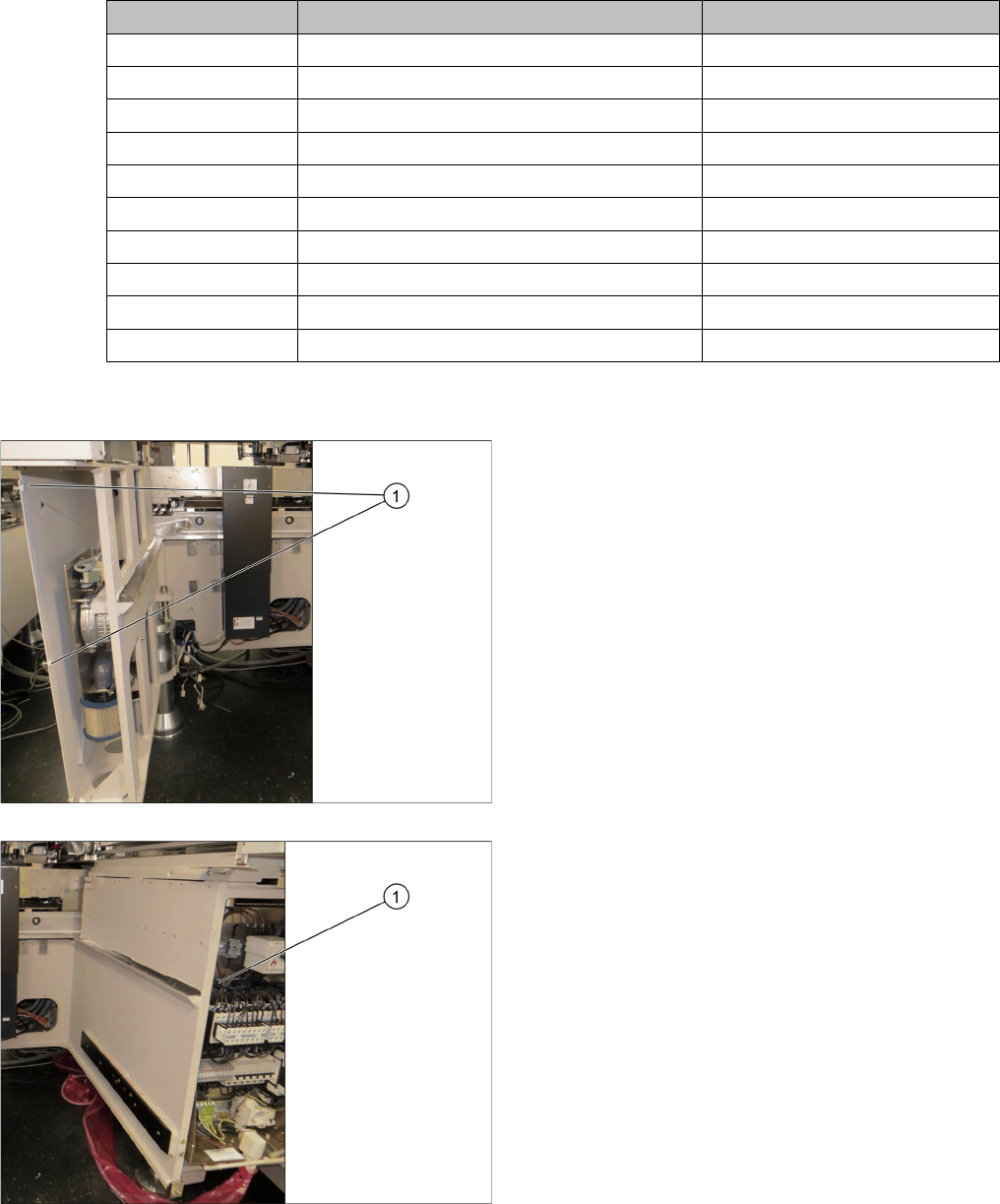
► Dismantle the side panel. Remove the four hexagon
socket screws (1).
► Loosen and remove the screws and then dismantle
the cover (1) of the power supply at location 3.
Setting up and Commissioning
Retrofitting in the SIPLACE X-Series S 4.3.3 Removing the COT insert
122 JEDEC Tray Feeder
4.3.3
4.3.3 Removing the COT insert
Removing the COT insert
The COT insert must be removed before installing the manual table.
► Dismantle the nozzle changer.
► Disconnect the COT insert from all electrical and pneumatic connections. Mark the positions of these
connections, to make clear assignment easier later on. The connection cables and hoses are located
behind the COT insert – in the space leading to the machine base (under the nozzle changer).
CAUTION
Heavy machine part!
Risk of injuries die to heavy weight.
➢ The COT insert is heavy.
► To lift it out, use the fit-up aid and a suitable lifting device (hand-operated crane etc.).
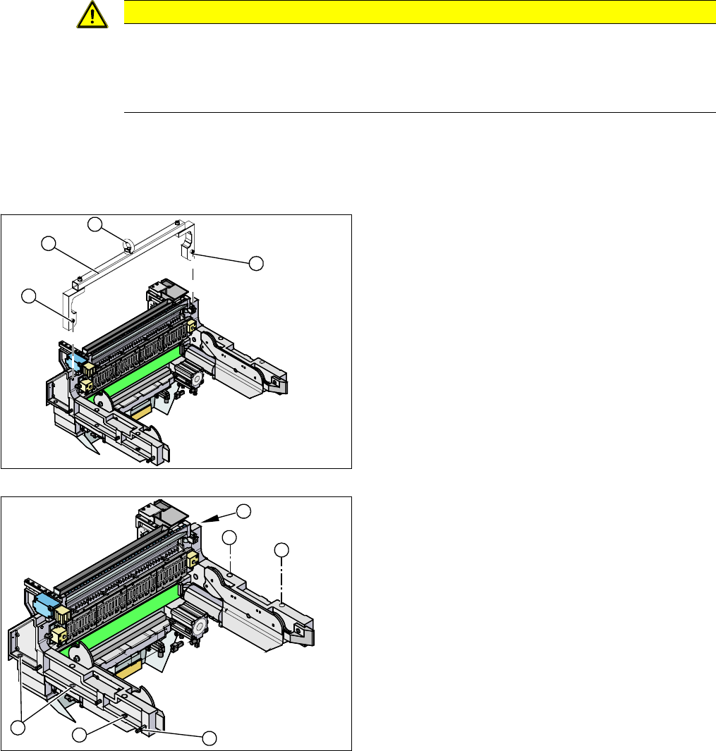
1. Fixtures
2. Fit-up aid
3. Eyelet
► Attach the fit-up aid (2) to the fixtures provided (1) on
the COT insert.
► Fix the lifting device to the eyelet (3) of the fit-up aid
(2).
► Loosen the screws fastening the COT insert (1).
► Lift the complete COT insert out of the machine and
place it on a suitable surface (e.g. four wooden
blocks).
► Make sure that you do not damage any valves, con-
nection cables, hoses etc.
1
1
3
2
1
1
1
1
2
1
Setting up and Commissioning
4.3.4 Installation Position of the Spacer Plates for Reject Boxes, Stationary Camera and Q10 Magazine at Locations 2 and 3 Retrofitting in the
JEDEC Tray Feeder 123
4.3.4
4.3.4 Installation Position of the Spacer Plates for Reject Boxes, Stationary Camera and Q10 Magazine at Locations 2 and 3
Installation Position of the Spacer Plates for Reject Boxes, Stationary Camera and Q10
Magazine at Locations 2 and 3
Observe the different installation positions of the spacer plates for the installation of the reject box, the
stationary camera and the Q10 magazine. These vary, depending on location and machine type.
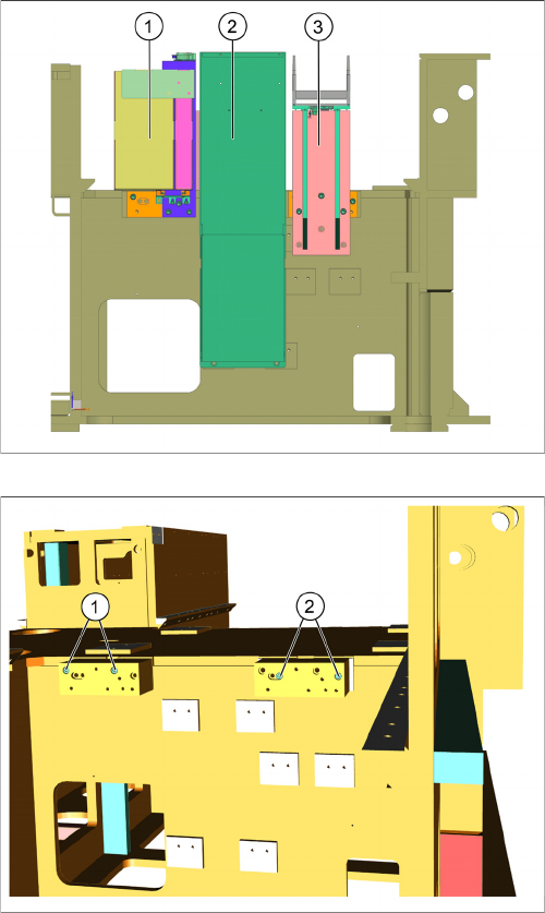
Positions on the SIPLACE X2 S, X3 S and SIPLACE X4 S at location 2
1. Reject box
2. Stationary camera
3. Q10 magazine
1. Installation position for the reject box
2. Installation position for the Q10 magazine