00197446-02_UM_JTF_S_JTF-M_ X-Serie_S_de_en.pdf - 第127页
Setting up and Commissioning 4.3.5 Installing the Mounting Plate for the Reject Box Retrofitt ing in the SIPLACE X-Series S JEDEC Tray Feeder 127 ► Fix the reject box holder [03106722 -xx] (1) to the mounting plate [0310…
Setting up and Commissioning
Retrofitting in the SIPLACE X-Series S 4.3.5 Installing the Mounting Plate for the Reject Box
126 JEDEC Tray Feeder
Positions on the SIPLACE X4i S at location 3
4.3.5
4.3.5 Installing the Mounting Plate for the Reject Box
Installing the Mounting Plate for the Reject Box
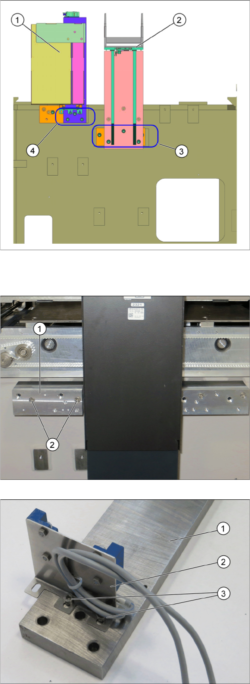
1. Installation position for the reject box
2. Installation position for the Q10 magazine
3. Screw points for the Q10 magazine
4. Screw points for the reject box
► Fix the spacer plate for the reject box [03104724-xx]
(1) to the machine base using the two M6x70 screws
(2).
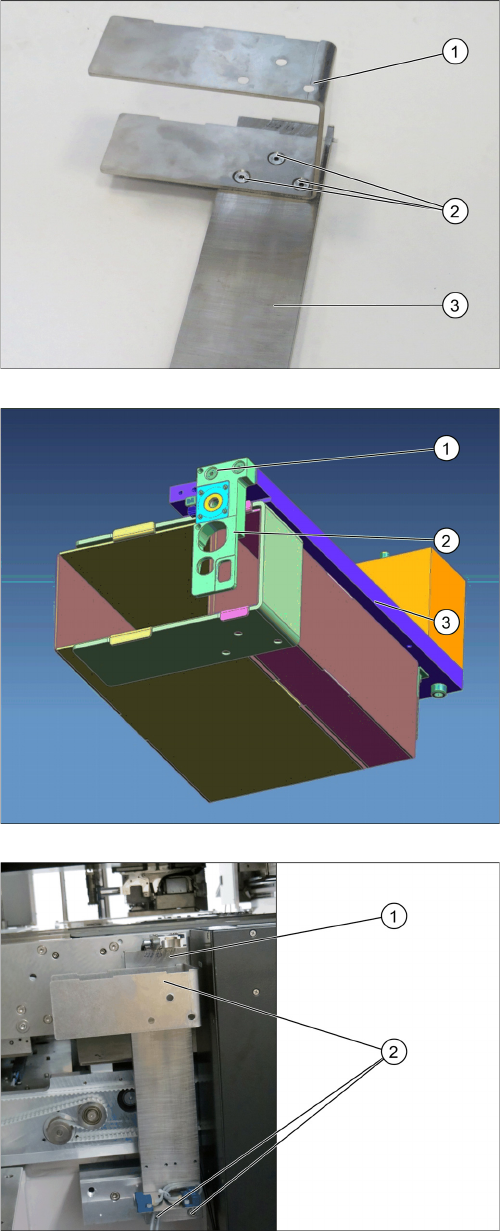
► Fix the query sensor assy X-series S JTF table
[03107486-xx] (2) to the mounting plate [03104561--
xx] (1) using the two M4x6 (3) screws.
Setting up and Commissioning
4.3.5 Installing the Mounting Plate for the Reject Box Retrofitting in the SIPLACE X-Series S
JEDEC Tray Feeder 127
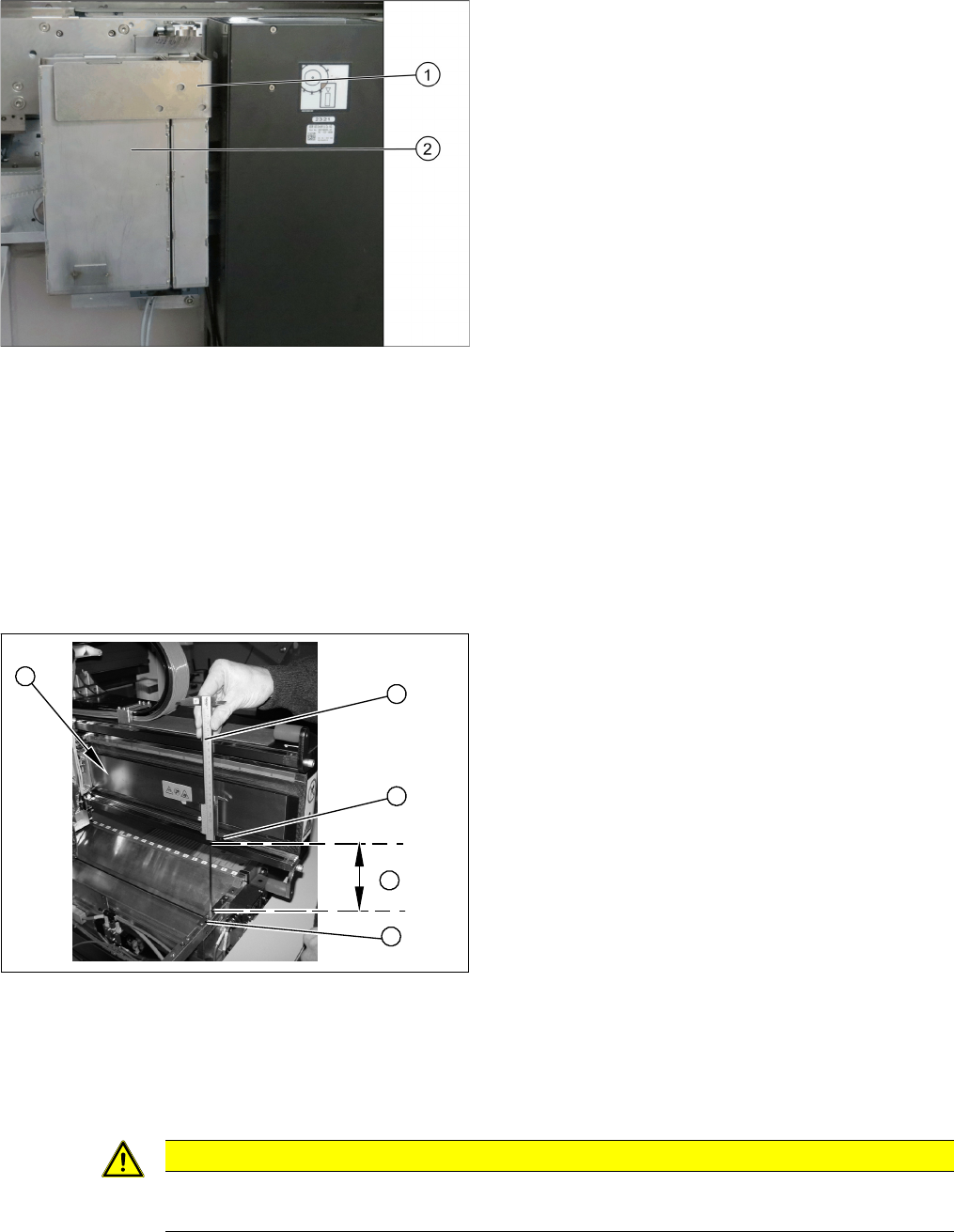
► Fix the reject box holder [03106722-xx] (1) to the
mounting plate [03104561-xx] (3) using the three
countersunk M4x10 screws (2).
► Fix the nozzle station [03106821-xx] upport f. nozzle
reject device [03104731-xx] and the three Shim f.
nozzle reject devices [03104733-xx] ( (2) to the
mounting plate [03104561-xx] (3) using the two
screws (1).
After setting up the insert, the nozzle station has to be
supplied with the compressed air pulse.
► Fix the mounting plate [03104561-xx] (1) to the spac-
er plate using the three M2x25 screws (2).
Setting up and Commissioning
Retrofitting in the SIPLACE X-Series S 4.3.6 Setting the Nozzle Changer Height
128 JEDEC Tray Feeder
► Check the height of the nozzle station.
4.3.6
4.3.6 Setting the Nozzle Changer Height
Setting the Nozzle Changer Height
Parts, equipment and tools
▪ Measuring scale
▪ NC shim plate [03021079-xx]
Overview
Setting
► During the following inside measurement, make sure that the tip of the measuring scale does not
tough the magnetic strip, as this might scratch it!
► Position the measuring scale (1) on the top edge of the X axis lower linear guide (2) and measure
the distance to the nozzle changer contact surface (4).
► Hold the measuring scale vertically (1).
► Hook the reject box small cpl. [03106818-xx] and the
reject box large cpl.[ 03106815-xx] (2) into the holder
[03106722-xx] (1).
Overview of measurement procedure
1. Measuring scale
2. Top edge of the X axis lower linear guide
3. Values to be set (150 +/- 0.2 mm)
4. Nozzle changer contact surface
5
1
4
3
2
CAUTION
Strong magnetic forces
Place a suitable plastic plate between the magnet and measuring scale.