00197446-02_UM_JTF_S_JTF-M_ X-Serie_S_de_en.pdf - 第134页
Setting up and Commissioning Retrofitting in the SIPLACE X-Series S 4.3.8 Installing the Manual Table 134 JEDEC Tray Feeder 4.3.8.3 4 . 3 . 8 . 3 P n e u m a t ic C o n n e c t io n Pneumatic Connection 4.3.8.4 4 . 3 . 8…
Setting up and Commissioning
4.3.8 Installing the Manual Table Retrofitting in the SIPLACE X-Series S
JEDEC Tray Feeder 133
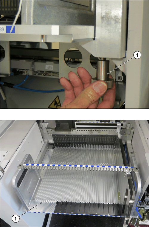
► Fasten the screws (1) to fix the back part to the frame.
► If necessary, remove the plastic feeder guide profiles
(1) of the tracks onto which the adapter is to be
placed.
Setting up and Commissioning
Retrofitting in the SIPLACE X-Series S 4.3.8 Installing the Manual Table
134 JEDEC Tray Feeder
4.3.8.3
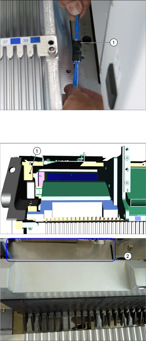
4.3.8.3 Pneumatic Connection
Pneumatic Connection
4.3.8.4
4.3.8.4 Installing the Hand Guard at the Cutting Device
Installing the Hand Guard at the Cutting Device
A hand guard must be installed at the cutting device for safety reasons.
► Connect the hose coming from the machine to the
coupling of the back part (1).
1x PUN 8 [03095247-xx] → 2x PUN 6 [03095246-xx]
► Fix the hand guard [03108706-xx] (2) to the table
frame using the M6x10 screw (1).
Setting up and Commissioning
4.3.9 Connecting Cables Installation
JEDEC Tray Feeder 135
4.3.9
4.3.9 Connecting Cables
Connecting Cables
► Refit the tape cutter.
► Refit the waste slide welded complete [03067460-xx].
► Push the tape reel container MT 40 [03082711-xx] under the fixed table.
► Push the waste container 530x650x200 mm cmpl. [03088978-xx] under the tape reel container MT
40.
► At last, refit the side cover.
4.3.10
4.3.10 Fitting the Short Cover Handle to the Cover at Location 3
Fitting the Short Cover Handle to the Cover at Location 3
► Replace the existing cover handle at location 3 with the new cover handle [03113231-xx].
4.4
4.4 Installation
Installation
The following chapters briefly describe the installation of the adapter and of the SIPLACE JTF-S,
SIPLACE JTF-M.
4.4.1
4.4.1 Assembling the X Adapter for JEDEC Tray Feeder
Assembling the X Adapter for JEDEC Tray Feeder
The adapter has to be installed on specific tracks:
▪ SIPLACE X-Series S = track 1 – 15 at location 3
▪ SIPLACE X-Series S = track 27 – 40 at location 2
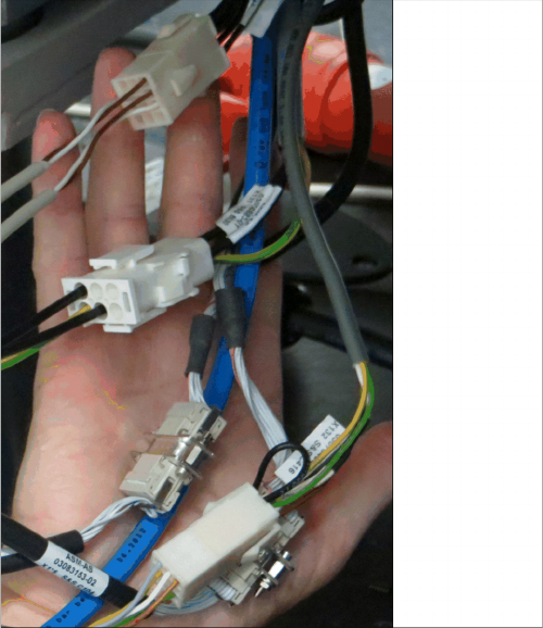
► Connect the cables as follows:
▪ 03083152-xx: => X1*2 =>2 (Signaling) (in the ma-
chine to X1*2)
▪ 03083153-xx: => X 1*6 (Can1_Out)
▪ 03083148-xx: => X 1*11 (Power)
▪ 03083687-xx: => X 1*3 (Safety Circuit)
▪ 0308315x-xx: => X 1*5 (Can1_In)
► Connect the two cables for the query sensor.
► Connect the black hose to the reject station.