00197446-02_UM_JTF_S_JTF-M_ X-Serie_S_de_en.pdf - 第146页
Tasks for SIPLACE JTF-S, SIPLACE JTF-M Controls and Displays 5.2.1 Structure 146 JEDEC Tray Feeder 5.2 5 . 2 C o n t r o ls a n d D is p la y s Controls and Displays 5.2.1 5 . 2 . 1 S t r u c t u r e Structure The diagra…
Tasks for SIPLACE JTF-S, SIPLACE JTF-M
5.1.1 Setting the JEDEC Tray Delay Task: Operating the Feeder
JEDEC Tray Feeder 145
5.1.1
5.1.1 Setting the JEDEC Tray Delay
Setting the JEDEC Tray Delay
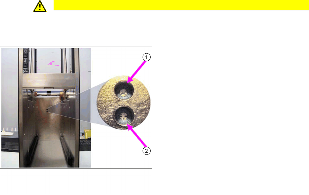
▪ Potentiometer delay (1):
Return slow down sensor
Clockwise: the conveyor ramp down delay is adjusted so that the tray arrives at the back more quick-
ly.
▪ Potentiometer delay (2):
Forward slow down sensor
Clockwise: the conveyor ramp down delay is adjusted so that the tray arrives at the front more quick-
ly.
See also the software manual for SIPLACE JEDEC tray feeder, [00197543-01]
CAUTION
Overrotating the potentiometer
These settings should be performed with care. If you overturn the potentiometer, you may need
to replace the entire control PCB.
To ensure that the JEDEC tray does not approach the
pick position too abruptly, a delay mechanism has been
fitted.
When the slow down sensors are passed, the delay be-
gins after the set time. This time can be set with the po-
tentiometer.
After the sensors have been passed, the controller con-
tinuously reduces the scanning degree of the motor con-
trol until the tray reaches the stop sensor. The speed of
the belt is also reduced.
If the tray moves forward, it passes the light barrier, the
forward slow down sensor. When moving backwards, it
passes the light sensor, the return slow down sensor.
The diagram shows the potentiometer and the setting for
it. This setting should only be made by trained personnel.
Tasks for SIPLACE JTF-S, SIPLACE JTF-M
Controls and Displays 5.2.1 Structure
146 JEDEC Tray Feeder
5.2
5.2 Controls and Displays
Controls and Displays
5.2.1
5.2.1 Structure
Structure
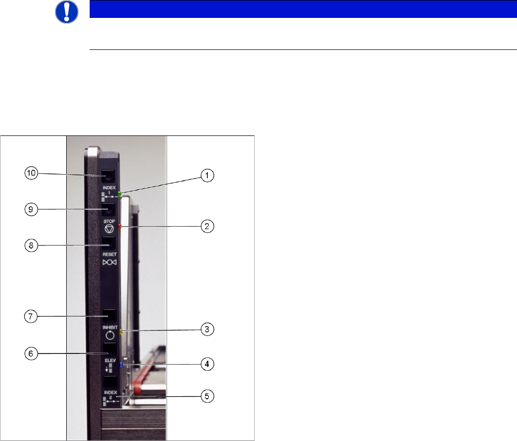
The diagram shows the control panel on the feeder.
The functions "Index, Inhibit and Elevator Down" are regulated by the controller.
The functions "Stop and Reset" are an electronic stopping function for the pneumatic system. If you
press the stop button, the pneumatic system immediately switches off and the motors will stop. The sta-
tus is read by the controller but not regulated by it.
NOTICE
SIPLACE JTF-S
This panel only applies to the SIPLACE JTF-S.
The precise functions are described below:
Index 1 (10) and index 2 (5)
Index 1 (10) and 2 (5) only trigger a tray changeover if
they are both pressed (series connection). The next tray
in the series is moved into the magazine. A connection to
the serial interface is needed for the various feeder com-
mands.
This function is disabled in production mode.
Stop (9)
If you press the stop button (9), the pneumatic system im-
mediately switches off and the motors will stop. The stop
button supports the stopping function of the pneumatics
system. A signal is sent to the host.
The "Stop and Reset" functions can not be switched off
by the production mode.
Reset (8)
The reset button (8) resets the feeder after a stop condi-
tion. A signal is sent to the host.
The "Stop and Reset" functions can not be switched off
by the production mode.
Inhibit (7)
The inhibit button (7) locks the remote control for the
SIPLACE JTF-S. The feeder does not receive any control
commands from the host. This lock is released when the
button is pressed again.
This function is disabled in production mode.
Elevator down (6)
This function allows you to change the trays in the maga-
zine without stopping production. The magazine moves
down and the current tray in the pick position remains
clamped and the ready LED (green) continues to shine.
► As soon as the lift stops at the bottom, the door can
be opened and the trays can be changed.
► Open the door once the lift has reached the bottom.
► Leave the empty slot (for the tray currently used in the
pick position) empty.
This function is disabled in production mode.
Tasks for SIPLACE JTF-S, SIPLACE JTF-M
5.2.1 Structure Controls and Displays
JEDEC Tray Feeder 147
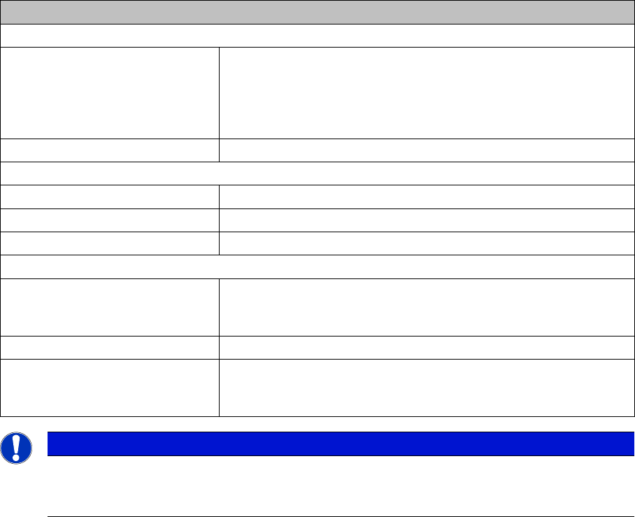
LED indicators
Green LED – READY (1)
LED on Shows that a tray was successfully moved to the pick position and
is now ready for components to be removed from the tray (or for it
to be loaded). The LED also shows that a ready signal has been
sent to the host. As soon as the tray leaves the pick position, the
LED will extinguish.
LED off Not ready for loading or unloading or tray changeover.
Orange LED – Stop/Error (2)
LED on Stop condition. For example, occurs after stop button was pressed.
LED flashes Error condition. An error occurred during the tray changeover.
LED off Normal mode
Yellow LED – Inhibit (3)
LED on The yellow LED shows a lock. The feeder will not receive any tray
changeover commands, neither via the remote control nor manual-
ly.
LED off Normal mode.
Blue LED – Full/Empty (4) If the next tray is manually queried after the last tray in the maga-
zine (slot with the highest number), the blue LED will show EMPTY.
This also occurs when there is no magazine inserted.
NOTICE
SIPLACE JTF-M
The SIPLACE JTF-M is only operated via the SC GUI. The only exception is the Reset button
on the operating panel, which can be used for the reset function.