03217917-01-01E By DEK Technical Reference Manual Vol 1_enPDFA.pdf - 第156页
11 SQUEEGEE MODULE 11.3 REPLACEMENT PROCEDURES 156 TECHNICAL REFERENCE MANUAL Vol 1 E By DEK 04/2019 11.3 REPLACEMENT PROCEDURES 11.3.1 Drive Belt Replacement There are two different types of squeegee stepper motors that…
11 SQUEEGEE MODULE
11.2 ELECTRICAL SCHEMATIC
TECHNICAL REFERENCE MANUAL Vol 1 E By DEK 04/2019 155
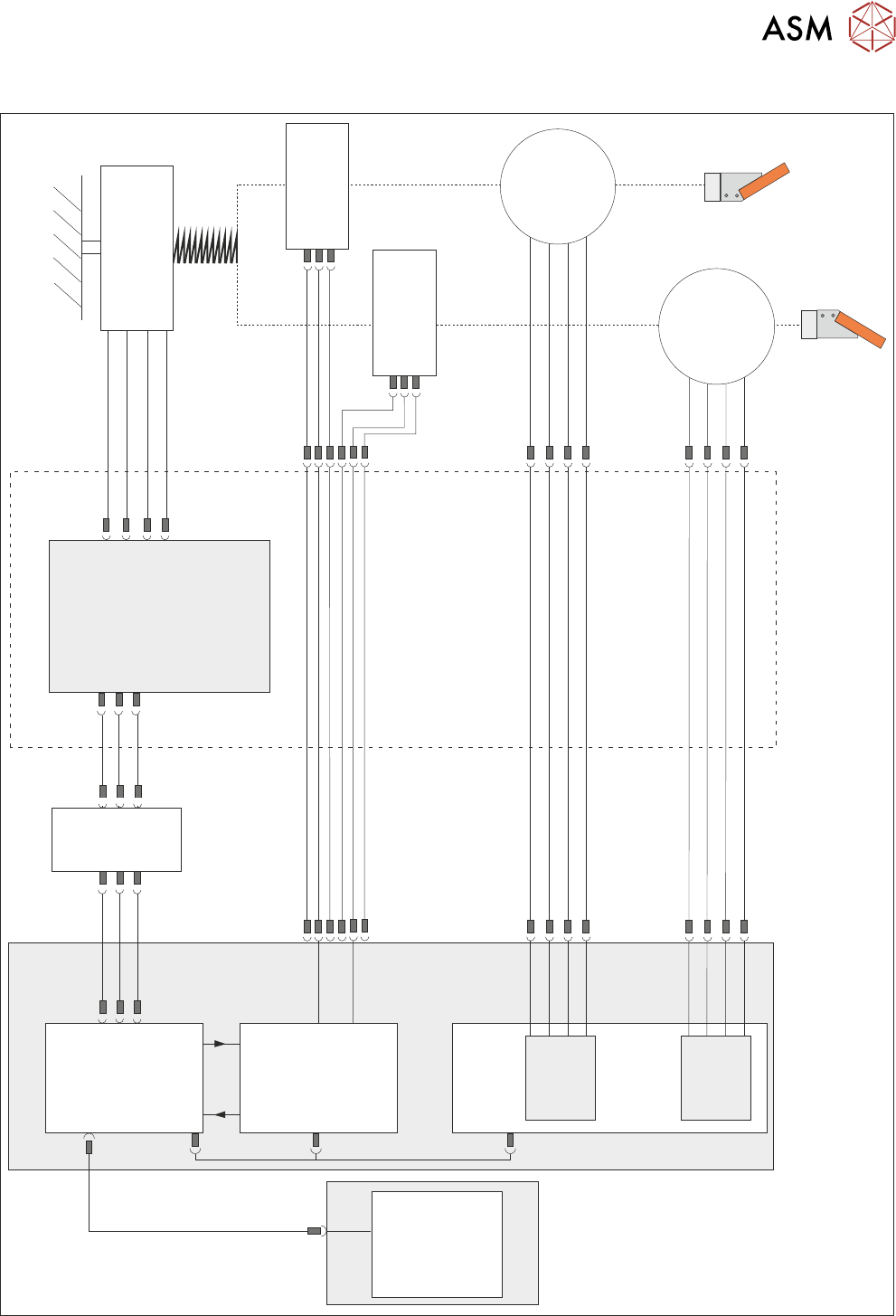
11.2 ELECTRICAL SCHEMATIC
Squeegee Front
Home
(9SE04)
Squeegee Rear
Home
(9SE05)
Rear
Squeegee
Stepper
Motor
(9M4)
Motor 1 B-
Motor 1 B+
Motor 1 A-
Motor 1 A+
Motor 2 B-
Motor 2 B+
Motor 2 A-
Motor 2 A+
Print Carriage
9PL16
9PL08
9PL17
0V
+V
-IN
+IN
Strain Gauge Bridge
(9SE6)
Spring Beam
9SK11
9SK12
Print Carriage I/O
Node 3
N3PL16
M36PL35
N3SK2
N6PL3
CAN BUS
PC
Motherboard
M36PL35
USB
M36Pl28
NextMove ES
(I/O Node 1)
NextMove
Interface
Dual Stepper
Card X2
M36 Machine Control
Step 3
Step 4
Front
Squeegee
Stepper
Motor
(9M3)
M36PL21
M36PL12
M36PL21
CAN
In
Rising
Table
Node 6
N6SK2
11 SQUEEGEE MODULE
11.3 REPLACEMENT PROCEDURES
156 TECHNICAL REFERENCE MANUAL Vol 1 E By DEK 04/2019
11.3 REPLACEMENT PROCEDURES
11.3.1 Drive Belt Replacement
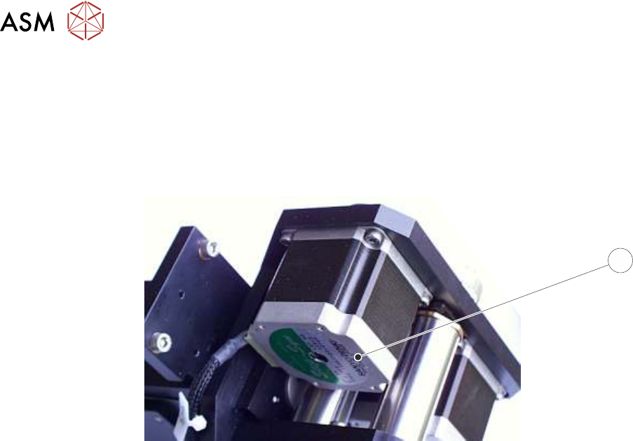
There are two different types of squeegee stepper motors that drive the drive belts, one type featur-
ing a green ident label (1) on the underside which requires tensioning of the belts, the other type
without the label which does not require tensioning.
1
Squeegee Stepper Motor (Green Ident Label Shown)
The belt replacement procedures for the two types are different, so care must be taken to ensure
the correct procedure is followed.
11.3.1.1 Rear Squeegee Drive Belt (Green Label)
The rear squeegee drive belt (right hand stepper motor) can be replaced without having to remove
the printhead mechanism from the print carriage.
► Select Open Cover Commands.
► Select Carriage To Front.
► Select Back.
► Select Shut Down.
► Select Continue.
► Switch the mains isolator to OFF; lockout the isolator switch.
► Open the printhead cover.
► Remove the squeegees, if fitted.
11 SQUEEGEE MODULE
11.3 REPLACEMENT PROCEDURES
TECHNICAL REFERENCE MANUAL Vol 1 E By DEK 04/2019 157
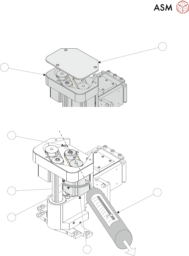
► Remove the drive belt cover plate (1) from the squeegee printhead mechanism (2) and
remove the broken drive belt.
1
2
► Slacken off the three screws (6) securing the right hand motor (4) to the motor support plate.
7
6
5
4
3
► Fit the new belt in position.
► Using a cable tie wrap (5) or similar, provide a loop around the top of the body of the motor (4)
enabling the motor to be pulled using a force meter (3). Ensure that the force meter is pulled
in the direction which the drive belt is fitted, figure above refers.
► Pull the force meter (3) until a tension of 3-4kgs is monitored on the meter. Tighten the three
screws (6) whilst the motor is under tension.
► Refit the squeegees.
► Close the printhead cover.
► Remove the isolator lock; turn the mains isolator switch ON.
► Press the System button.