03217917-01-01E By DEK Technical Reference Manual Vol 1_enPDFA.pdf - 第41页
4 COVERS 4.1 PRINTER COVERS TECHNICAL REFERENCE MANUAL Vol 1 E By DEK 04/2019 41 4.1.1.7 Rear Corner Panels To remove either of the rear corner panels, carry out the following: ► Remove the Left Hand Safety Cover (as det…
4 COVERS
4.1 PRINTER COVERS
40 TECHNICAL REFERENCE MANUAL Vol 1 E By DEK 04/2019
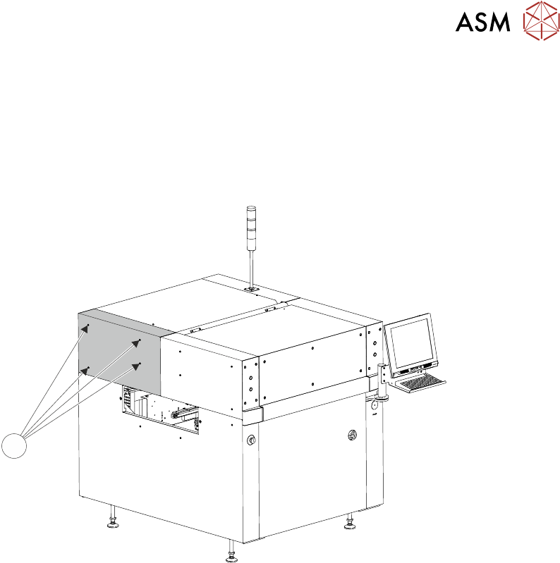
4.1.1.5 Upper Rear Panel
To remove the upper rear panel, carry out the following:
► Using a 4mm Allen key, undo the four captive screws (1).
1
1
► Lift the panel clear of the printer frame, taking care not to damage the earth cable.
4.1.1.6 Safety Covers
Safety covers are fitted to the side panels to protect personnel from inadvertent access to the
board entry/exit ports.
To remove the safety cover, remove the two securing screws (1).
1
4 COVERS
4.1 PRINTER COVERS
TECHNICAL REFERENCE MANUAL Vol 1 E By DEK 04/2019 41
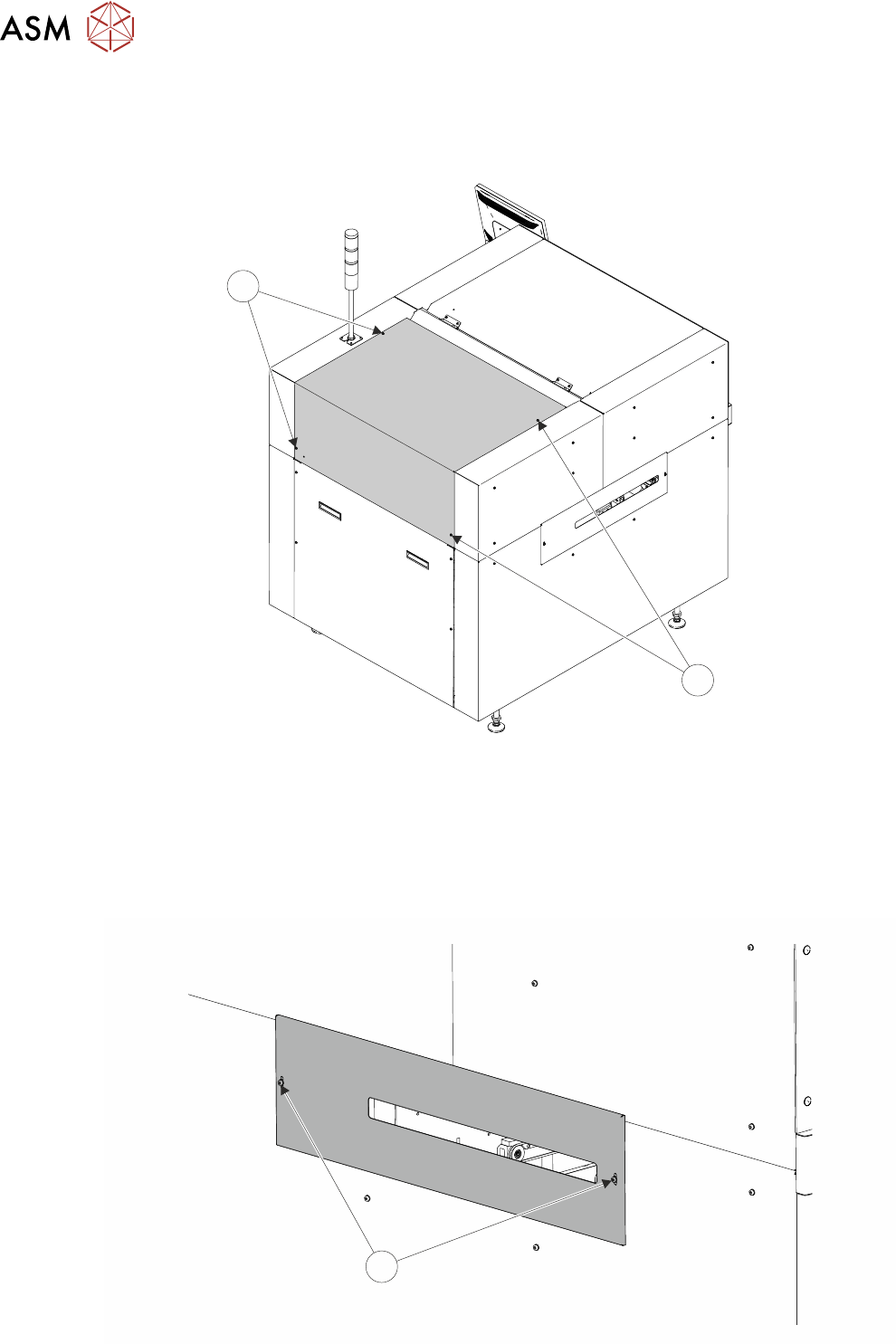
4.1.1.7 Rear Corner Panels
To remove either of the rear corner panels, carry out the following:
► Remove the Left Hand Safety Cover (as detailed previously).
► Remove the Right Hand Safety Cover (as detailed previously).
► Using a 4mm Allen key, undo the appropriate four captive screws (1).
► Lift the panel clear of the printer frame, taking care not to damage the earth cable.
1
4 COVERS
4.1 PRINTER COVERS
42 TECHNICAL REFERENCE MANUAL Vol 1 E By DEK 04/2019
4.1.1.8 Upper Front Corner Panels
To remove the upper front corner panels, carry out the following:
► Open the front printhead cover.
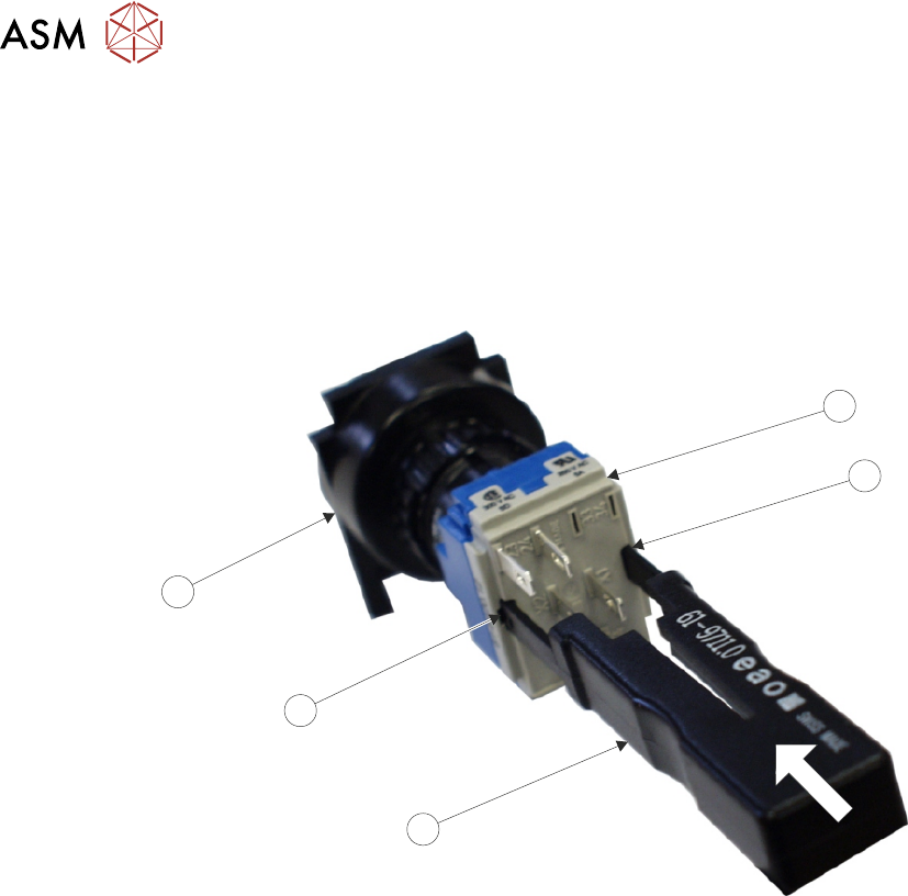
► Locate the control switches (jog switch and system switch) attached to the panel.
► To disconnect the system switch and jog buttons carry out the following:
► Locate the two release slots (2) in the contact assembly (1) part of the switch.
3
2
4
2
1
► Insert the switch release tool (Part No 188647) (3) into the slots and push until the release tool
clicks into place.
► Leaving the switch release tool in position, pull the contact assembly (1) from the switch body
(4).
► Remove the switch release tool (3) from the contact assembly.
► Using a 4mm Allen key, undo the appropriate four captive screws (5).
► Remove the panel clear of the machine, taking care not to damage the earth cable.