03217917-01-01E By DEK Technical Reference Manual Vol 1_enPDFA.pdf - 第275页
17 CAMERA SYSTEM MODULE 17.4 REPLACEMENT PROCEDURES TECHNICAL REFERENCE MANUAL Vol 1 E By DEK 04/2019 275 4 3 1 2 1 Dovetaill Fixings Remain in Place 3 Camera Connectors 2 Camera Mount (with Camera Removed) 4 Camera Secu…

17 CAMERA SYSTEM MODULE
17.4 REPLACEMENT PROCEDURES
274 TECHNICAL REFERENCE MANUAL Vol 1 E By DEK 04/2019
17.4 REPLACEMENT PROCEDURES
17.4.1 Camera
WARNING
BOARD CLAMPS. EXTREME CARE MUST BE EXERCISED WHEN WORKING IN
THE TOOLING AREA OF THE MACHINE TO AVOID INJURY. THE FOILS ON THE
FRONT AND REAR BOARD CLAMPS ARE VERY SHARP.
17.4.1.1 Removal
► Select Open Cover Commands.
► Select Carriage To Rear.
► Select Back.
► Select Shut Down.
► Select Continue.
► Switch the mains isolator to OFF and lockout the isolator.
► Open the printhead cover.
► Remove the stencil.
► To gain access to the camera for removal, move the camera forward and central over the
table by manually moving the camera carriage.
► Remove the following connectors from the rear of the camera unit:
●
10SK17
●
10SK13
► Loosen the two camera mount screws and lift the dovetail fixings to free the camera, lift the
camera out of the camera mount.

17 CAMERA SYSTEM MODULE
17.4 REPLACEMENT PROCEDURES
TECHNICAL REFERENCE MANUAL Vol 1 E By DEK 04/2019 275
4
3
1
2
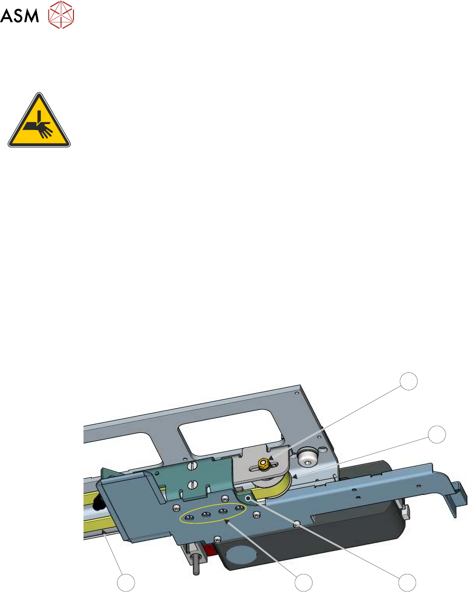
1 Dovetaill Fixings Remain in Place 3 Camera Connectors
2 Camera Mount
(with Camera Removed)
4 Camera Securing Screws
17.4.1.2 Fitment
► Slide the camera into position in the dovetail ensuring that the end of th camera mount butts
against the right hand side of the dovetail and secure camera mount screws (2).
► Connect 10SK13 and 10SK17.
► Ensure that the cable-ties are secure and the cables are positioned to prevent any chaffing on
the board clamps or transport rails.
► Refit the stencil.
► Close the printhead cover.
► Remove the lock from the isolator.
► Power up the machine.
► Select Load Screen.
► The following adjustments/calibrations must be carried out:
●
Camera Reference Position Adjustment
●
Board Stop X Offset Check Calibration
●
Vision Calibration
17 CAMERA SYSTEM MODULE
17.4 REPLACEMENT PROCEDURES
276 TECHNICAL REFERENCE MANUAL Vol 1 E By DEK 04/2019
●
Calibrate Offset Calibration
17.4.2 Camera X Axis Timing Belt
WARNING
BOARD CLAMPS. EXTREME CARE MUST BE EXERCISED WHEN WORKING IN
THE TOOLING AREA OF THE MACHINE TO AVOID INJURY. THE FOILS ON THE
FRONT AND REAR BOARD CLAMPS ARE VERY SHARP.
► Select Maintenance.
► Select Diagnostics.
► Select Exit.
NOTE
Exiting diagnostics initialises the machine, homing the camera axes.
► Select Back.
► Select Shut Down.
► Select Continue.
► Switch the mains isolator to OFF and lock the isolator.
► Open the printhead cover.
► Remove the stencil from the machine.
► Remove the left and right side panels.
► Slacken the idle pulley locknut (1) at the left hand end of the camera carriage.
1
2
3
4
5
► Slide the pulley (2) inwards to release tension on the timing belt (5).
► Slacken the four timing belt clamp securing screws (4) sufficiently to remove the timing belt (5)
from the clamp (3).
NOTE
Take note of the routing of the timing belt before removing it.
► Remove the timing belt and discard.
► Route the replacement timing belt around the camera X motor pulley and the idle pulley.
► Engage the two ends of the replacement timing belt equally into the timing belt clamp. Tighten
the timing belt clamp screws sufficiently to allow belt movement. Ensure the timing belt is
straight between the two pulleys and the timing belt clamp.