03217917-01-01E By DEK Technical Reference Manual Vol 1_enPDFA.pdf - 第278页
17 CAMERA SYSTEM MODULE 17.4 REPLACEMENT PROCEDURES 278 TECHNICAL REFERENCE MANUAL Vol 1 E By DEK 04/2019 1 1 3 10 ► Using a tension meter (10) (Part No. 190279), check the timing belt (11) tension either side of the cab…
17 CAMERA SYSTEM MODULE
17.4 REPLACEMENT PROCEDURES
TECHNICAL REFERENCE MANUAL Vol 1 E By DEK 04/2019 277
► Fully tighten the timing belt clamp screws.
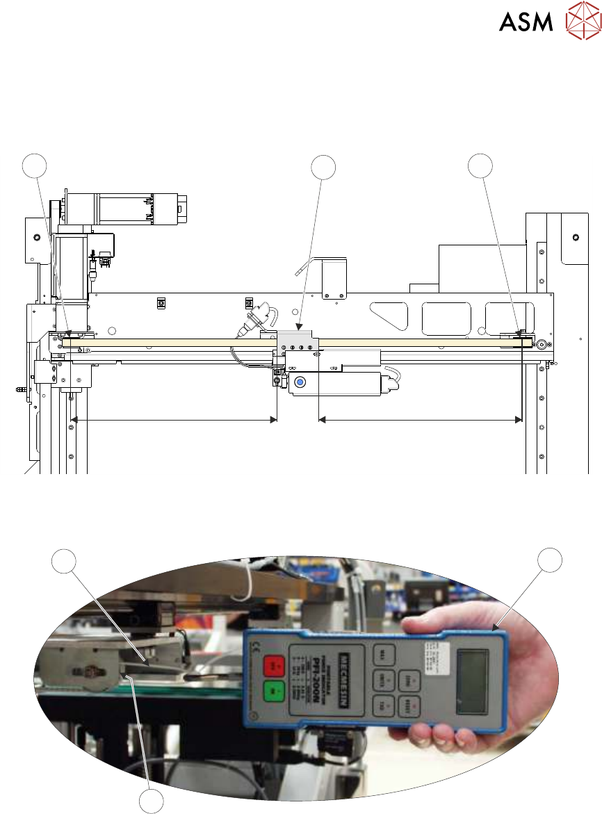
► Manually position the timing belt clamp (3) on the camera X axis timing belt so that the dis-
tance X1 (camera X motor pulley (7) to timing belt clamp (3)) is equal to the distance X2 (tim-
ing belt clamp (3) to idle pulley (6)).
X1 X2
7
3
6
► Using a suitable cable tie (9), engage a forcemeter (8) across the idle pulley (6). Apply a hori-
zontal force of 24kg to the belt. Maintaining this force, tighten the locknut (1).
24.0 kg
9
8
6
► Remove the forcemeter (8). Do not remove the cable tie (9) as further adjustment may be ne-
cessary.
► Ensure that the belt clamp (3) is midway between the two pulleys.
17 CAMERA SYSTEM MODULE
17.4 REPLACEMENT PROCEDURES
278 TECHNICAL REFERENCE MANUAL Vol 1 E By DEK 04/2019
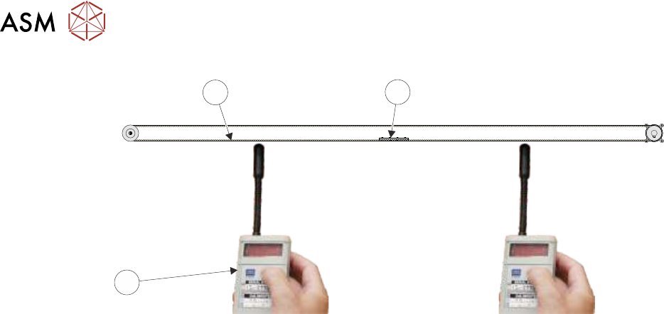
11
3
10
► Using a tension meter (10) (Part No. 190279), check the timing belt (11) tension either side of
the cable clamp (3) is between 52Hz and 58Hz. Check the two readings are within 1Hz of
each other.
NOTE
Adjust the position (between the two pulleys) of the belt clamp to achieve the 1Hz deviation.
► If adjustment is not required, go to Correct Tension.
► If adjustment is required, slacken the idle pulley locknut (1).
► Adjust the timing belt tension using the cable tie (9).
► Tighten the locknut (1).
► Repeat until the correct tension is achieved.
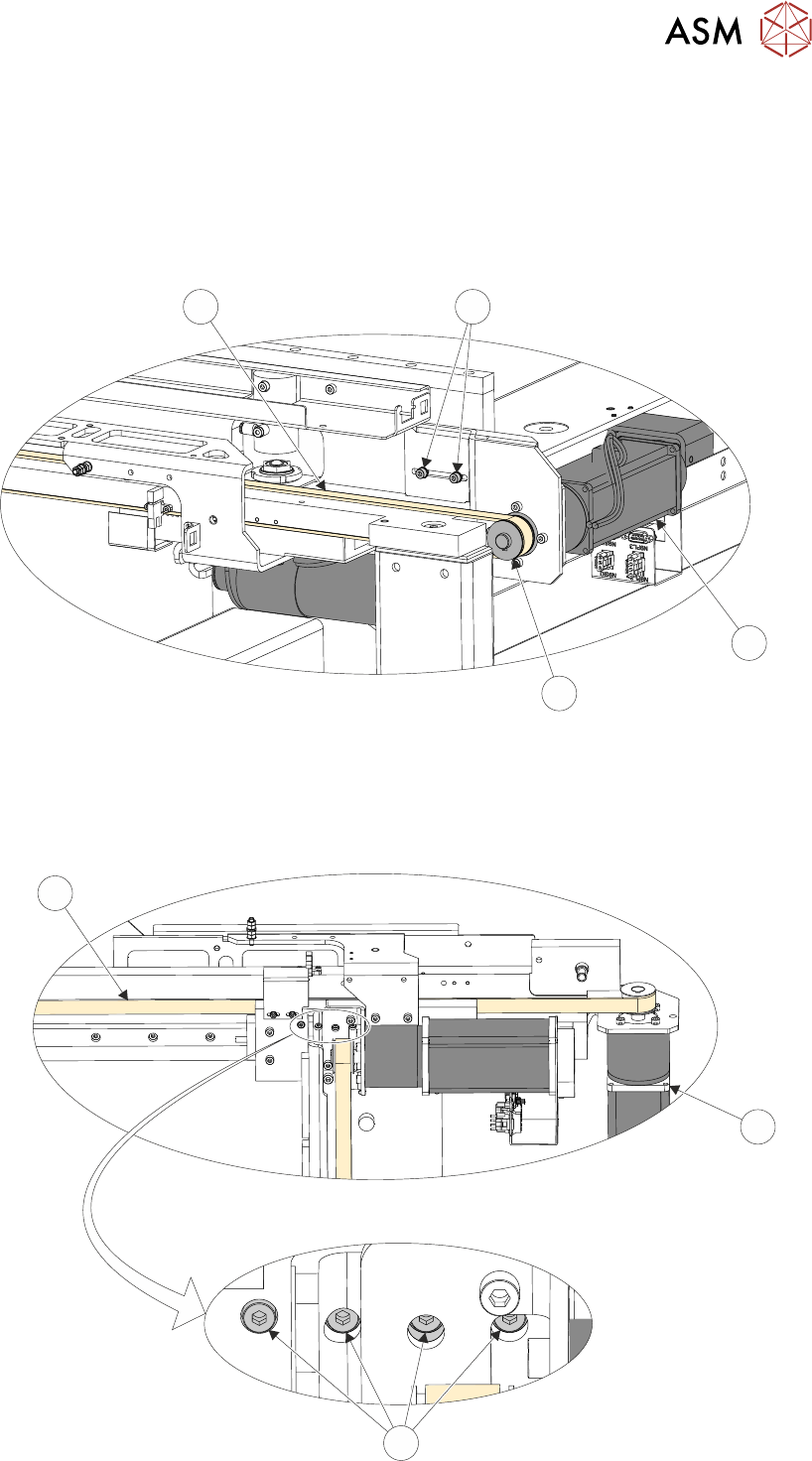
► Correct Tension - Remove the timing belt clamp securing screws (4) one at a time, apply a
suitable locking compound and fully tighten.
► Remove the cable tie (9).
► Refit the panels removed.
► Remove the lock from the isolator.
► Power up the machine and press the System button to initialise.
► Select Maintenance.
► Select Diagnostics.
► Using the Next or Previous button highlight Camera Axes.
► Select Select Module.
► Using the Next or Previous button highlight Home Camera X Axis.
► Select Correct Tension.
► Using the Next or Previous button highlight Home Camera y Axis.
► Select Run Diagnost.
► Carry out the following checks:
●
Camera Reference Position.
●
Calibrate Vision.
17.4.3 Camera Y Axis Timing Belt
► Select Maintenance.
► Select Diagnostics.
► Select Exit.
NOTE
Exiting diagnostics initialises the machine, homing the camera axes.
► Select Back.
17 CAMERA SYSTEM MODULE
17.4 REPLACEMENT PROCEDURES
TECHNICAL REFERENCE MANUAL Vol 1 E By DEK 04/2019 279
► Select Shut Down.
► Select Continue.
► Switch the mains isolator to OFF and lock the isolator.
► Remove the right hand machine side panel.
► Loosen the two securing screws (4), slide the motor (1) towards the machine frame releasing
the tension on the timing belt (3).
3
4
1
2
► Slacken the four timing belt clamp securing screws (5) sufficiently to remove the timing belt (3)
from the clamp (8).
NOTE
Take note of the routing of the timing belt before removing it.
3
1
5