03217917-01-01E By DEK Technical Reference Manual Vol 1_enPDFA.pdf - 第241页
16 TRANSPORT RAILS MODULE 16.4 ADJUSTMENTS AND SETTINGS TECHNICAL REFERENCE MANUAL Vol 1 E By DEK 04/2019 241 1 2 2 250mm Board Clamp Mechanism ► Adjust the board clamp to achieve the setting of 0.325mm +/-0.025mm betwee…
16 TRANSPORT RAILS MODULE
16.4 ADJUSTMENTS AND SETTINGS
240 TECHNICAL REFERENCE MANUAL Vol 1 E By DEK 04/2019
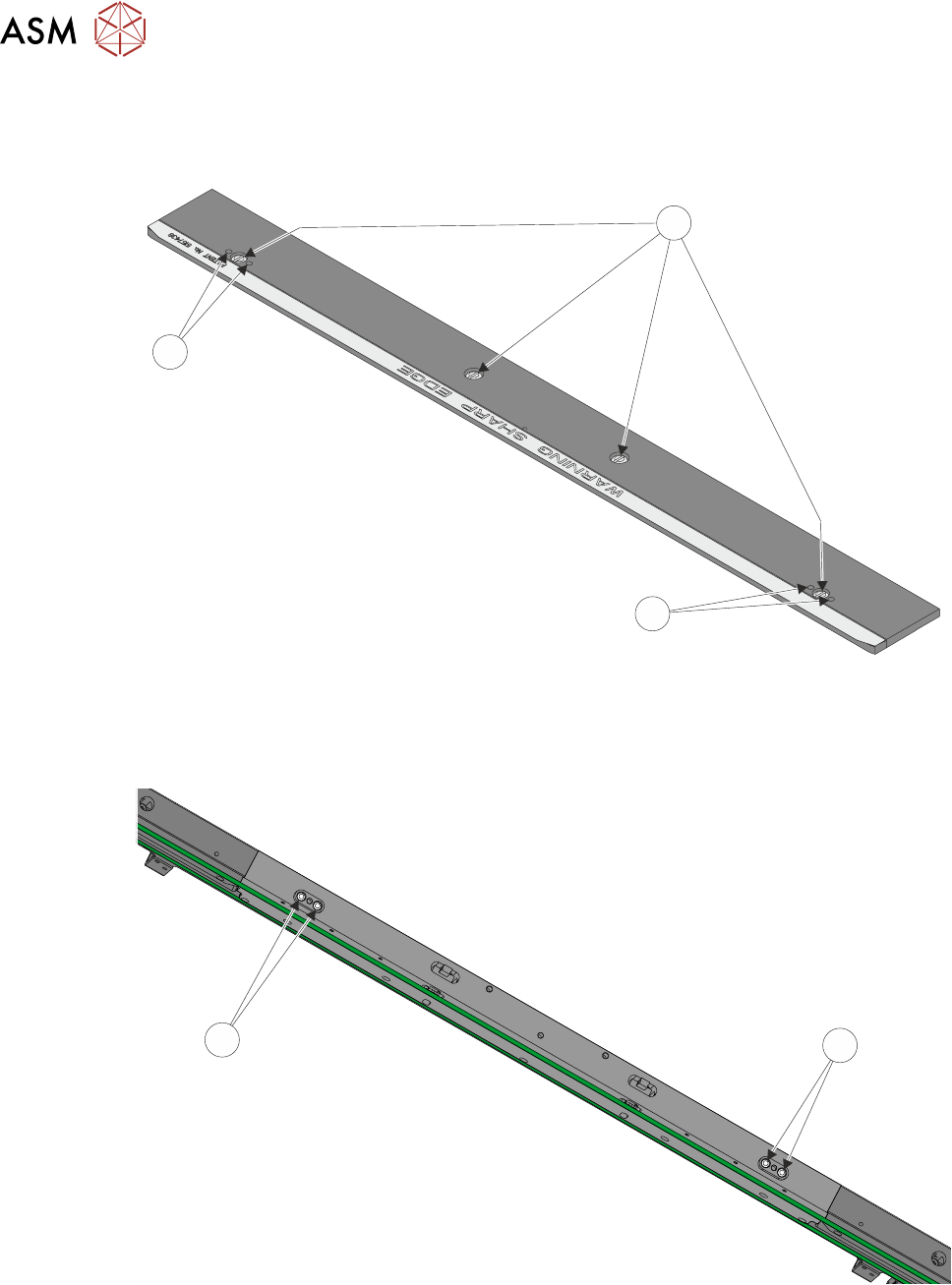
Rear Board Clamp Gap Adjustment
► 500mm Board Clamps Only. Remove the four board clamp securing screws (1) and lift off the
board clamp. Retain the four screws (1).
1
2
2
500mm Board Clamp Mechanism
► 500mm Board Clamps Only. Slacken the two location plate securing screws (2).
2
2
► 500mm Board Clamps Only. Place the board clamp in position, but do not fit the securing
screws.
► 250mm Board Clamps Only. Slacken the two location plate securing screws through the
access slots.
16 TRANSPORT RAILS MODULE
16.4 ADJUSTMENTS AND SETTINGS
TECHNICAL REFERENCE MANUAL Vol 1 E By DEK 04/2019 241
1
2
2
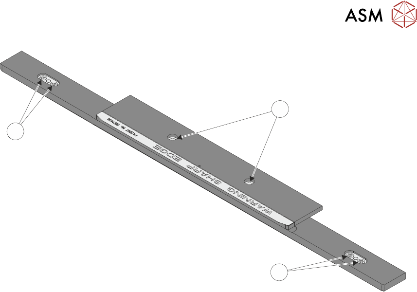
250mm Board Clamp Mechanism
► Adjust the board clamp to achieve the setting of 0.325mm +/-0.025mm between the rear
board clamp and the belt support plate.
► 500mm Board Clamps Only. When the correct setting has been achieved tighten the location
plate securing screws through the access holes in the board clamp, with a small bladed
screwdriver.
► 250mm Board Clamps Only. When the correct setting has been achieved tighten the location
plate securing screws through the access slots.
► Recheck that the gap between the rear board clamp and the belt support plate is 0.325mm
+/-0.025mm.
Front Board Clamp Gap Adjustment
► Repeat Rear Board Clamp Gap Adjustment procedure for the front board clamp.
Board Clamp Parallelism Check
► Using a vernier gauge check that the board clamps are parallel, to within 0.1mm, at the left,
centre and right of the board clamps.
► If adjustment is necessary, slacken the location plate securing screws on the rear rail and ad-
just. Tighten the location plate securing screws on completion.
► If any adjustment is carried out, ensure the board clamp gap set previously is maintained.
► 500mm Board Clamps Only. Lift off the rear rail board clamp and further tighten the location
plate securing screws, with a larger bladed screwdriver.
► 500mm Board Clamps Only. Place the rear rail board clamp in position and secure with the
four securing screws.
► 500mm Board Clamps Only. Repeat last two steps for the front rail.
► Refit the belt guide to either side of the rear rail belt support plate.
► Refit the belt guide to either side of the front rail belt support plate.
► Ensure correct operation of the board clamps after any adjustment is made.
16 TRANSPORT RAILS MODULE
16.4 ADJUSTMENTS AND SETTINGS
242 TECHNICAL REFERENCE MANUAL Vol 1 E By DEK 04/2019
16.4.4 Foil-less Clamp Height Adjustment
Foil-Less Clamps are height adjustable to accommodate for different board thickness. Adjust the
clamp height for the product to be printed.
► Select Open Cover Commands.
► Select Carriage To Rear.
► Select Unload Screen.
► Open the printhead cover.
► Remove the stencil from the machine.
► Place a product board centrally between the foil-less clamps.
► Close the printhead cover.
► Press the System button.
► Select Maintenance.
► Select Diagnostics.
► From the displayed table, using the Next or Previous button highlight RailSystem.
► Select Select Module.
► Using the Next or Previous button highlight Toggle Board Clamp.
► Select Run Diagnost.
► Open the printhead cover.
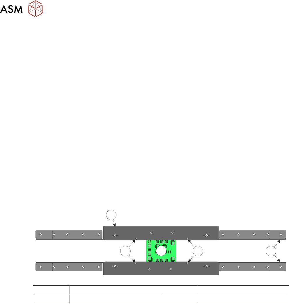
► Adjust the two downstop screws on each clamp such that the top of the board and clamp are
flush aligned.
4
2
3
2 1
1 Transport Belts 3 Board
2 Downstop Screws 4 Rear Foil-less Clamp
► Close the printhead cover.
► Press the System button.
► Select Run Diagnost. Check that the board is held without coming out of the rails.
► Select Adjust.
► Using the Next or Previous button highlight Cycle Count.
► Using the Incr. or Decr. button change the cycle count to 10.
► Select Exit.
► Using the Next or Previous button highlight Cycle Board Clamp.
► Select Run Diagnost. Ensure that the clamps open and close without disturbing the board.
► Ensure that once the cycle has finished the board clamps are Off. If not, using the Next or
Previous button highlight Toggle Board Clamp.
► Select Run Diagnost.
► Open the printhead cover.
► Refit the stencil.
► Remove the product board.