03217917-01-01E By DEK Technical Reference Manual Vol 1_enPDFA.pdf - 第165页
11 SQUEEGEE MODULE 11.4 CALIBRATIONS TECHNICAL REFERENCE MANUAL Vol 1 E By DEK 04/2019 165 ► Switch the force meter ON and check the reading is 0kg , (ensure the force meter is not in contact with the squeegee pressure p…
11 SQUEEGEE MODULE
11.4 CALIBRATIONS
164 TECHNICAL REFERENCE MANUAL Vol 1 E By DEK 04/2019
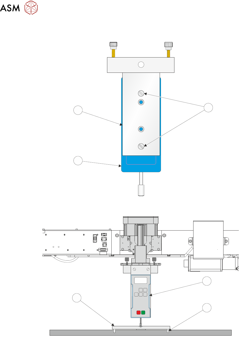
► Ensure that the calibration jig (2) is secured to the mounting plate (3) as shown in the follow-
ing graphic:
A
A
S
S
1
3
2
► Fit the calibration jig (4) to the front squeegee position.
O
OFF
I
ON
UNITS
Zero
MAX TXD
RESET
00.00
4
5
6
► Fit the squeegee pressure plate (6) to the rising table ensuring that the locating dowels (5) in-
sert the holes of the rising table.
NOTE
During the squeegee pressure calibration the dwell height of the rear squeegee is 15mm regard-
less of the set up value. This height is set during calibration only.

11 SQUEEGEE MODULE
11.4 CALIBRATIONS
TECHNICAL REFERENCE MANUAL Vol 1 E By DEK 04/2019 165
► Switch the force meter ON and check the reading is 0kg, (ensure the force meter is not in
contact with the squeegee pressure plate).
► Select Continue.
► The front squeegee mechanism steps down until a change in pressure is detected and contin-
ues stepping down until the pressure value stored on the machine is reached. If the calibration
jig displays 10kg, go to Calibration Complete.
► Select Jog Rig.
► Use the left and right jog buttons to move the front squeegee mechanism up or down until the
calibration jig displays 10kg.
NOTE
Achieving exactly 10kg may not be possible as some calibration jigs display down to three decimal
places.
Calibration Complete
► Select Set Calib..
► Select Exit.
► The front squeegee mechanism moves to the home position. The message ‘Confirm that the
pressure calibration jig has been removed.’ is displayed.
► Remove the calibration jig and the squeegee pressure plate from the machine. On completion
select Yes, the table resets, the print carriage moves to home position, board clamps open
and the rear rail moves to the board width setting.
► Carry out the 11.4.2 "Squeegee Reference Height (Pressure Feedback)" [}165] calibration.
11.4.2 Squeegee Reference Height (Pressure Feedback)
Squeegee reference height is carried out on machines fitted with the Pressure Hardware option
after the following circumstances:
●
Squeegee pressure calibration
●
Squeegee change
Use the following procedure to set the squeegee reference height:
► If a Ptest.dat file is required:
●
Select Maintenance.
●
Select Test Cycles.
●
Select Data Logging On.
●
Select Back.
●
Select Back.
► Select Setup Product.
► Select Squeegees.
► Select Unload Screen.
► Open the printhead cover.
► Remove the stencil from the machine.
► Close the printhead cover.
► Press the System button.
► Select Calibrate Heights.
► The message ‘Ensure that the correct squeegees are fitted!’ is displayed.
► Open the printhead cover.
► Fit the required squeegees to the front and rear squeegee mounts as detailed in the 11.3.2
"Fitting the Squeegees" [}161].
► Close the printhead cover.

11 SQUEEGEE MODULE
11.4 CALIBRATIONS
166 TECHNICAL REFERENCE MANUAL Vol 1 E By DEK 04/2019
► Press the System button.
► Select Continue.
► The following machine sequence is carried out:
●
The rails are checked for the presence of a board.
●
The rising table is driven to print height.
●
The board clamps are closed.
●
The print carriage drives the front squeegee over the front rail; see note.
●
The rear squeegee is driven down to dwell height.
●
The front squeegee is driven down by the stepper motor until contact with the board clamp is
made.
●
The front squeegee continues to be driven down until a 2kg pressure difference is detected,
the motor pauses.
●
The amount of steps (the stepper motor took to get to this position) and the pressure are re-
corded.
●
The stepper motor drives downwards another 15 steps, this is recorded with the pressure de-
tected. This is repeated a further 18 times to achieve a total of 20 results.
NOTE
If the incorrect squeegees are fitted or are poorly fitted the squeegees cannot be calibrated. A
panel is displayed warning the user to check the squeegees.
► The rear squeegee is calibrated in a similar manner.
► The message ‘Calibrate Squeegee heights complete’ is displayed.
► Select Back.
► Select Back.
► Select Maintenance.
► Select Test Cycles.
► Select Data Logging Off.
► Select Back.
► Select Back.
11.4.2.1 Ptest.dat File
The file displays 20 front squeegee readings followed by 20 rear squeegee readings, showing the
relationship between steps (displacement) and pressure applied. From the readings taken, the front
and rear pressure factors and squeegee reference heights are calculated. At the end of the file, 5
readings of flood pressure and reference height readings are displayed (these are also listed in the
Config.txt file).
The Ptest.dat file is located on the hard drive of the machine PC. To view the file carry out the fol-
lowing procedure:
► From the Windows start menu, select Programs - Accessories - WindowsExplorer.
► Under My Computer, locate and open the E:\Log\Ptest.dat file.
The following figure gives a representation of the Ptest.dat file.