03217917-01-01E By DEK Technical Reference Manual Vol 1_enPDFA.pdf - 第249页
16 TRANSPORT RAILS MODULE 16.4 ADJUSTMENTS AND SETTINGS TECHNICAL REFERENCE MANUAL Vol 1 E By DEK 04/2019 249 Adjustment ► Using a 3.0mm Allen key, loosen the four securing screws (6) that secure the right hand side bear…
16 TRANSPORT RAILS MODULE
16.4 ADJUSTMENTS AND SETTINGS
248 TECHNICAL REFERENCE MANUAL Vol 1 E By DEK 04/2019
1
2
3
► Checking both left and right, continue to manually move the rear rail to close the gap for a
snug (not tight) fit.
Paralleism Check
NOTE
If the rails are not parallel, one side makes contact before the other side. Go to Adjustment to ad-
just the rails.
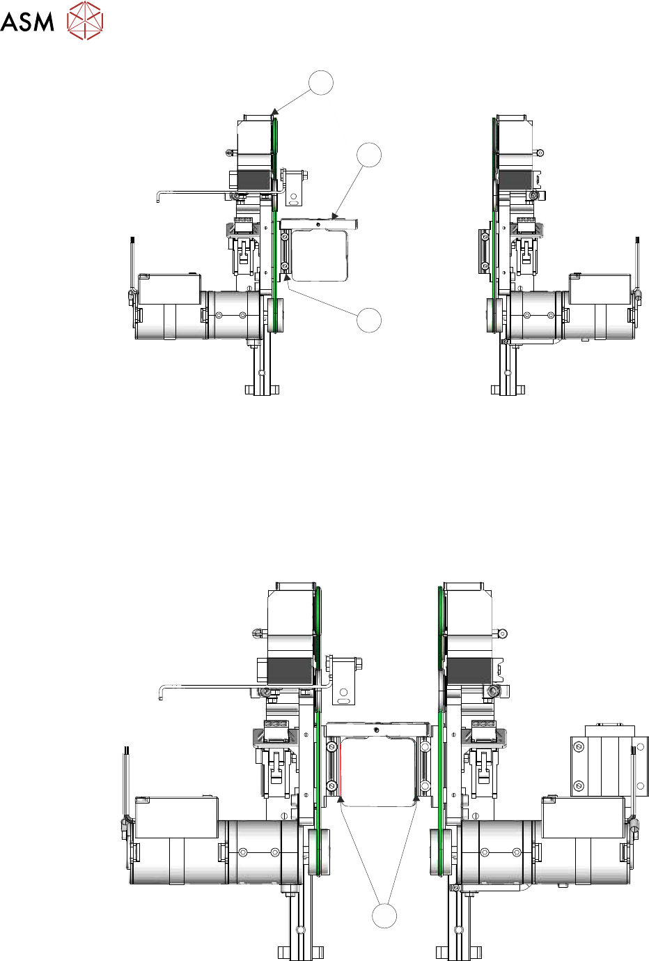
► Attempt to slide a 0.05mm feeler gauge between the rear bearing blocks (4) (left and right
hand side) and the transport rail tools (front and rear); as shown below:
4
► If both sets of linear guides are without gaps, the rear transport rail is parallel to the front rail,
go to Close Up.
16 TRANSPORT RAILS MODULE
16.4 ADJUSTMENTS AND SETTINGS
TECHNICAL REFERENCE MANUAL Vol 1 E By DEK 04/2019 249
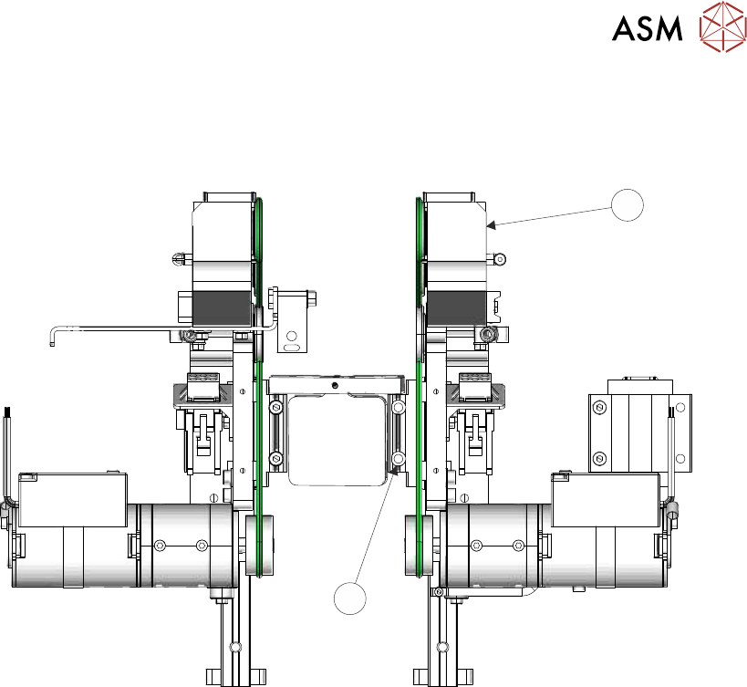
Adjustment
► Using a 3.0mm Allen key, loosen the four securing screws (6) that secure the right hand side
bearing block on the rear rail (5).
5
6
► Loosen the four securing screws that secure the left hand side bearing block on the rear rail
(5).
► Gently move the rear rail to close the gap on the appropriate side.
► Using the feeler gauge, check the left and right hand bearing blocks to ensure there is no gap.
► Tighten all eight upper securing screws and recheck for gaps.
Close Up
► Remove the transport rail tools.
► Refit the machine panels removed previously.
16.4.7 Board to Snugger Gap
This setting is used to ensure that the board runs freely when transported on the rails.
► Ensure that the calibration board product is loaded into the product file.
► Select Open Cover Commands.
► Select Carriage To Rear.
► Select Unload Screen.
► Open the printhead cover.
► Remove the stencil from the printer.
► Place the calibration board on the input transport rail belts. Manually move the board into the
tooling area of the printer. Check for any clicks or knocks where the board may catch on the
shoulders of the rail, or mid section modules. If tight areas are detected the rails should be ad-
justed.
► With the board in the tooling area, use a 0.2mm feeler gauge between the edge of the board
and the snugger plate. If the feeler gauge is either tight or loose, adjust the ‘Set Rail Board
Width Calibration’ accordingly.
► Manually remove the board.

16 TRANSPORT RAILS MODULE
16.4 ADJUSTMENTS AND SETTINGS
250 TECHNICAL REFERENCE MANUAL Vol 1 E By DEK 04/2019
► Close the printhead cover.
► Press the System button.
► Select Back.
► Select Maintenance.
► Select Calibrations.
► Select Classic Calibrations.
► Select Offset.
► Select Rail Width Offset. Open the rail width offset window.
► Select Incr. or Decr. to set the offset required to increase or decrease the rail width dimen-
sion.
► Place the calibration board on the input transport rail belts. Manually move the board into the
tooling area of the printer. Check for any clicks or knocks where the board may catch on the
shoulders of the rail, or mid section modules. If tight areas are detected the rails should be ad-
justed.
► With the board in the tooling area, use a 0.2mm feeler gauge between the edge of the board
and the snugger plate. If the feeler gauge is either tight or loose, adjust the ‘Set Rail Board
Width Calibration’ accordingly.
► Select Exit.
► Select Back.
► Select Diagnostics.
► Using the Next or Previous button highlight Cycle Board on Belts.
► Close the printhead cover.
► Press the System button.
► Select Maintenance.
► Select Diagnostics.
► Using the Next or Previous button highlight Cycle Board on Belts.
► Select Run Diagnost.
► Place the calibration board on the input transport rail belts.
► Select Auto Board and ensure the board runs through the entire length of the rail system for
10 complete cycles, without jamming or excessive clicking of the board edges.
► Select Stop.
► Select Exit.
16.4.8 Home Position Rail Width Check
Ensure that the board clamps are fitted and the Board Clamp Setting procedure (this section refers)
has been completed before carrying out the following procedure:
► Select Open Cover Commands.
► Select Carriage To Rear.
► Select Unload Screen.
► Open the front printhead cover.
► Remove the stencil from the machine.
► Close the front printhead cover.
► Press the System button.
► Select Maintenance.
► Select Diagnostics.
► Use Next or Previous to highlight Rail System.
► Select Select Module.
► Ensure that Home Rail Width is highlighted.