03217917-01-01E By DEK Technical Reference Manual Vol 1_enPDFA.pdf - 第158页
11 SQUEEGEE MODULE 11.3 REPLACEMENT PROCEDURES 158 TECHNICAL REFERENCE MANUAL Vol 1 E By DEK 04/2019 11.3.1.2 Front Squeegee Drive Belt (Green Label) To replace the front squeegee drive belt (left hand stepper motor), th…
11 SQUEEGEE MODULE
11.3 REPLACEMENT PROCEDURES
TECHNICAL REFERENCE MANUAL Vol 1 E By DEK 04/2019 157
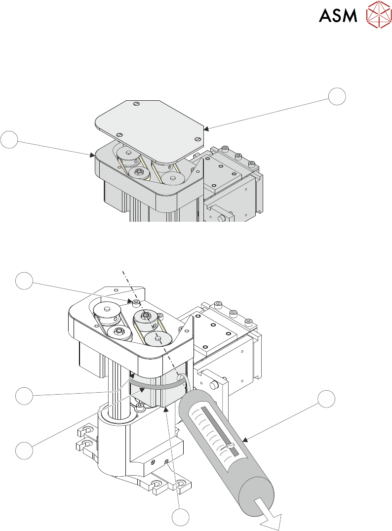
► Remove the drive belt cover plate (1) from the squeegee printhead mechanism (2) and
remove the broken drive belt.
1
2
► Slacken off the three screws (6) securing the right hand motor (4) to the motor support plate.
7
6
5
4
3
► Fit the new belt in position.
► Using a cable tie wrap (5) or similar, provide a loop around the top of the body of the motor (4)
enabling the motor to be pulled using a force meter (3). Ensure that the force meter is pulled
in the direction which the drive belt is fitted, figure above refers.
► Pull the force meter (3) until a tension of 3-4kgs is monitored on the meter. Tighten the three
screws (6) whilst the motor is under tension.
► Refit the squeegees.
► Close the printhead cover.
► Remove the isolator lock; turn the mains isolator switch ON.
► Press the System button.
11 SQUEEGEE MODULE
11.3 REPLACEMENT PROCEDURES
158 TECHNICAL REFERENCE MANUAL Vol 1 E By DEK 04/2019
11.3.1.2 Front Squeegee Drive Belt (Green Label)
To replace the front squeegee drive belt (left hand stepper motor), the printhead mechanism must
be removed from the print carriage.
► Select Open Cover Commands.
► Select Carriage To Front.
► Select Back.
► Select Shut Down.
► Select Continue.
► Switch the mains isolator to OFF; lockout the isolator switch.
► Open the printhead cover.
► Remove the squeegees, if fitted.
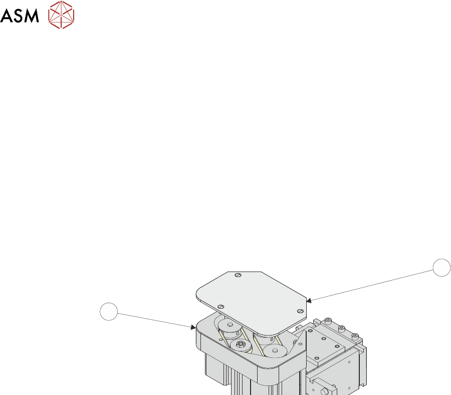
► Remove the drive belt cover plate (1) from the squeegee printhead mechanism (2) and
remove the broken drive belt.
1
2
► Disconnect the following connectors from the print carriage, left hand side.
●
Rear Squeegee Motor
●
Front Squeegee Motor
●
Home Sensors
●
Squeegee Pressure Amplifier
11 SQUEEGEE MODULE
11.3 REPLACEMENT PROCEDURES
TECHNICAL REFERENCE MANUAL Vol 1 E By DEK 04/2019 159
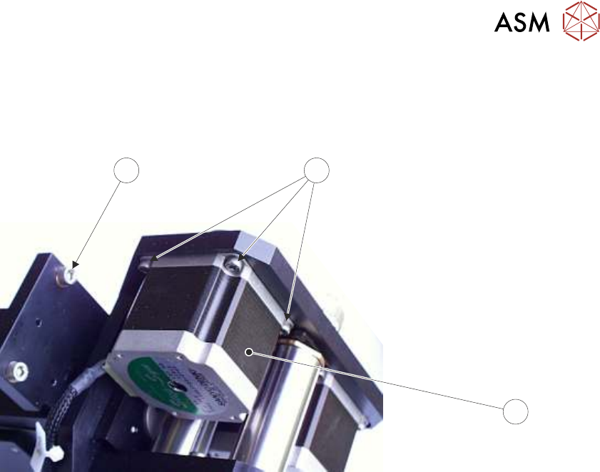
► Remove the printhead mechanism by unscrewing the four screws (4) securing the unit to the
print carriage.
► Placing the unit on a secure surface, slacken off the three screws (5) securing the left hand
motor (3) to the support plate.
4
5
3
Squeegee Stepper Motor (Green Ident Label Shown)
► Fit the new belt in position.
► Using a cable tie wrap or similar, provide a loop around the top of the body of the motor en-
abling the motor to be pulled using a force meter. Ensure that the force meter is pulled in the
direction which the drive belt is fitted, 11.3.1.1 "Rear Squeegee Drive Belt (Green La-
bel)" [}156] figure example refers.
► Pull the force meter until a tension of 3-4kgs is monitored on the meter. Tighten the three
screws (5) whilst the motor is under tension.
► On completion re-fit the printhead mechanism to the print carriage refit the drive belt cover
plate and re-connect all leads to the print carriage, left hand side.
► Refit the squeegees.
► Close the printhead cover.
► Remove the isolator lock; turn the mains isolator ON.
► Press the System button.