03217917-01-01E By DEK Technical Reference Manual Vol 1_enPDFA.pdf - 第193页
15 BOARD STOP 15.2 CAMERA MOUNTED BOARD STOP TECHNICAL REFERENCE MANUAL Vol 1 E By DEK 04/2019 193 A product (board) is fed into the printer and passes the Board at Left/Right Sensor. The board con- tinues on the transpo…
15 BOARD STOP
15.2 CAMERA MOUNTED BOARD STOP
192 TECHNICAL REFERENCE MANUAL Vol 1 E By DEK 04/2019
15.2 CAMERA MOUNTED BOARD STOP
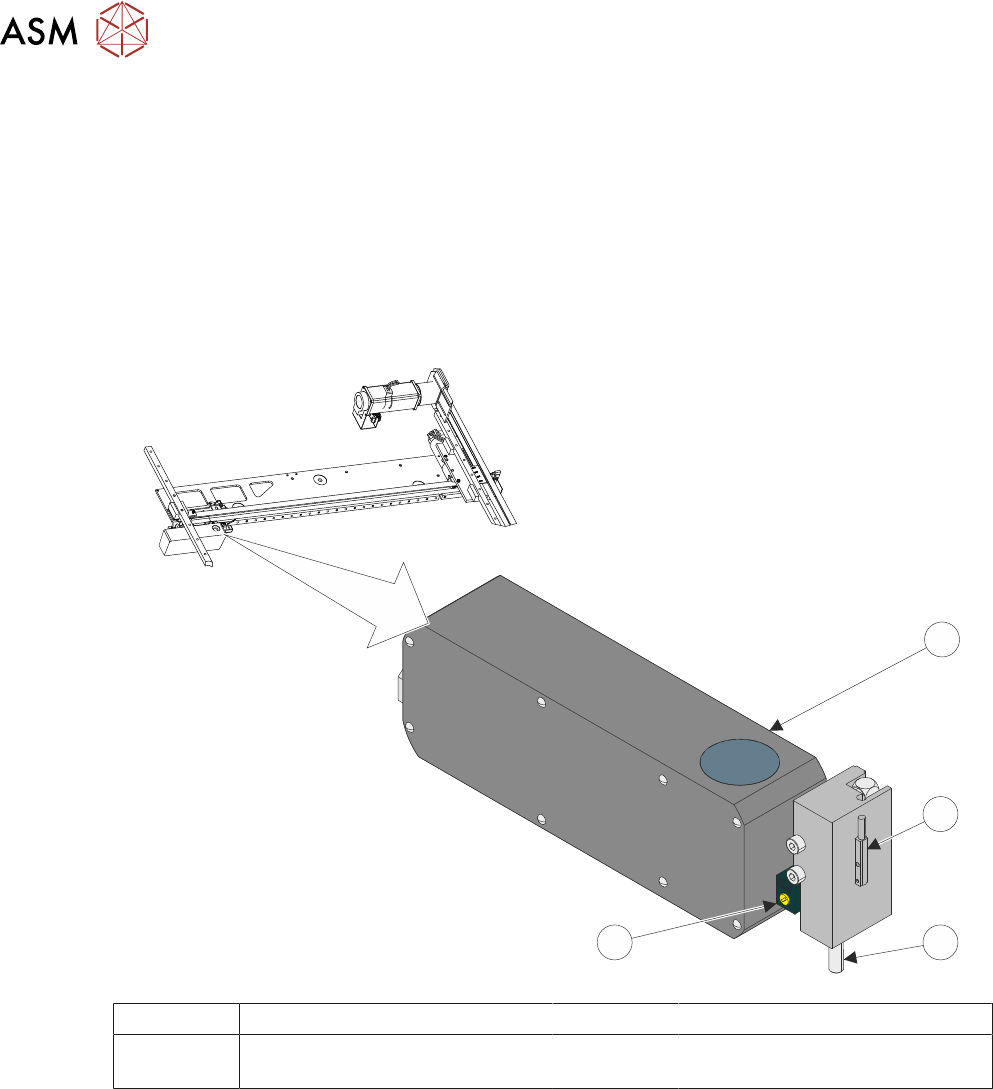
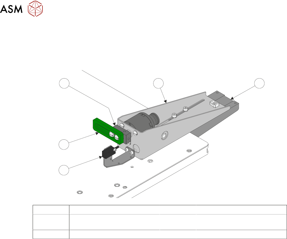
The camera is mounted on the camera carriage. The camera mounted board stop is fitted to the
right hand side of the camera. It is used to stop the product that is being loaded into the printer, at
the correct location in the X axis.
For details of the drive system refer to 17 "CAMERA SYSTEM MODULE" [}263].
The board stop assembly consists of the following components:
●
Camera Board Stop Actuator and Pin
●
Board at Stop Sensor
●
Board Stop Pin Extended Sensor
1
2
4
3
1 Camera 3 Board Stop Pin
2 Board Stop Pin Extended Sensor
(Internal)
4 Board At Stop Sensor
The camera board stop is a pneumatically driven unit which is lowered to stop the board in position
ready for clamping and vision alignment to take place.
The board at stop diffuse background suppressed opto detects the board when it reaches the
board stop. This starts a timer which when elapsed stops the belts and clamps the board.
The board stop extended sensor is fitted to ensure that the board stop is raised before any camera
carriage movement is demanded.

15 BOARD STOP
15.2 CAMERA MOUNTED BOARD STOP
TECHNICAL REFERENCE MANUAL Vol 1 E By DEK 04/2019 193
A product (board) is fed into the printer and passes the Board at Left/Right Sensor. The board con-
tinues on the transport rails; at the same time, the camera carriage moves the camera to the loca-
tion where the centre of the board (in X) is aligned to the centre of the white reference dot on the
front rail board clamp (see Note 1). The board, approaching the stop pin, triggers the Board at Stop
Sensor (see Note 2). The pneumatically driven board stop fires the stop pin down; the control sys-
tem reads the state of the Board Stop Extended Sensor and knows that the board can be stopped
in the correct place. The transport rail belts stop, ensuring that the board abuts the stop pin. The
board is in the correct position for printing.
NOTES
1. If the board feed is from Right to Left, the board is fed beyond the Board at Stop Sensor be-
fore its direction is reversed. It is then fed back toward stop pin as described previously.
2. If boards have irregularly shaped leading edges, the position of the stop must ensure that the
centre in the X axis is set as described for a plain surfaced board.
3. If the stop pin does not work the Board at Stop Sensor may need to be adjusted.
15 BOARD STOP
15.3 REMOTE MOUNTED BOARD STOP
194 TECHNICAL REFERENCE MANUAL Vol 1 E By DEK 04/2019
15.3 REMOTE MOUNTED BOARD STOP
The board stop is fitted to the rising table; this assembly is used to aid transportation of heavier
product than can be positioned using the camera board stop assembly.
The remotely mounted board stop can be assembled to stop the product which has been fed into
the printer from either the left hand or right hand side.
1
5
4
3
2
1 Base Clamp 4 Board Stop Rotary Arm
2 Board At Stop Sensor 5 Board Stop Assembly
(shown in RHS Configuration)
3 Board Stop
A product (board) is fed into the printer and passes the Board at Left/Right Sensor. The board con-
tinues on the transport rails; at the same time the camera carriage moves the camera to the loca-
tion where the centre of the board (in X) is aligned to the centre of the white reference dot on the
front rail board clamp (see Note 1). The board, approaching the remote board stop, triggers the
Board at Stop Sensor (see Note 2). The pneumatically driven board stop rotary arm, rotates the
board stop, the control system reads the state of the actuator reed switch and knows that the board
can be stopped in the correct place. The transport rail belts stop, ensuring that the board abuts the
board stop. The board is in the correct position for printing.
NOTES
1. If the board feed is from Right to Left, the board is fed beyond the Board at Stop Sensor be-
fore its direction is reversed. It is then fed back toward stop pin as described previously.
2. If boards have irregularly shaped leading edges, the position of the stop must ensure that the
centre in the X axis is set as described for a plain surfaced board.
3. If the board stop does not work the Board at Stop Sensor may need to be adjusted.