03217917-01-01E By DEK Technical Reference Manual Vol 1_enPDFA.pdf - 第50页
5 MACHINE OVERVIEW 5.1 MODULE OVERVIEWS 50 TECHNICAL REFERENCE MANUAL Vol 1 E By DEK 04/2019 5.1.2 Power Supply Module The M37 power supply enclosure fulfils the following functions: ● Transform and rectify the mains vol…
5 MACHINE OVERVIEW
5.1 MODULE OVERVIEWS
TECHNICAL REFERENCE MANUAL Vol 1 E By DEK 04/2019 49
5
MACHINE OVERVIEW
5.1 MODULE OVERVIEWS
This chapter describes the function and the purpose of each of the printer modules, their location
within the printer and the relationship and interaction between modules, if applicable.
For detailed information regarding each module refer to the relevant module chapter in this manual.
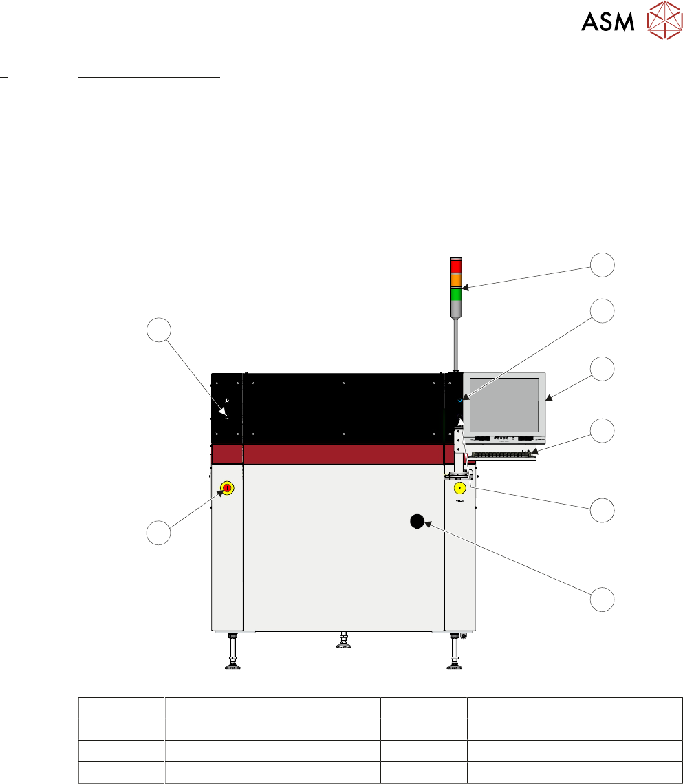
5.1.1 Man Machine Interface (MMI) Module
The MMI module enables communication and interaction between the user and the machine.
5
8
7
5
6
4
3
2
1
1 Tricoloured Beacon 5 Control Button
2 Control Button 6 Mains Isolator Switch
3 Monitor 7 Emergency Stop (E Stop)
4 Keyboard/Trackball Mouse 8 Control Button
5 MACHINE OVERVIEW
5.1 MODULE OVERVIEWS
50 TECHNICAL REFERENCE MANUAL Vol 1 E By DEK 04/2019
5.1.2 Power Supply Module
The M37 power supply enclosure fulfils the following functions:
●
Transform and rectify the mains voltage supply to the voltages required by the electrical sys-
tems throughout the machine.
●
Electrical safety – achieved by the use of emergency stop safety circuits (E Stop). When an E
Stop is activated, power is removed from selected areas of the machine.
5.1.3 Printer Control Module
The M36 machine control enclosure is the central hub controlling machine motion. Machine control
also consists of I/O nodes throughout the machine connected to the machine control enclosure us-
ing a CAN Bus.
Machine control is an interface between the software and:
●
Stepper Motors
●
Servo Motors
●
Sensors
●
Switches
●
Solenoids
●
Lamps
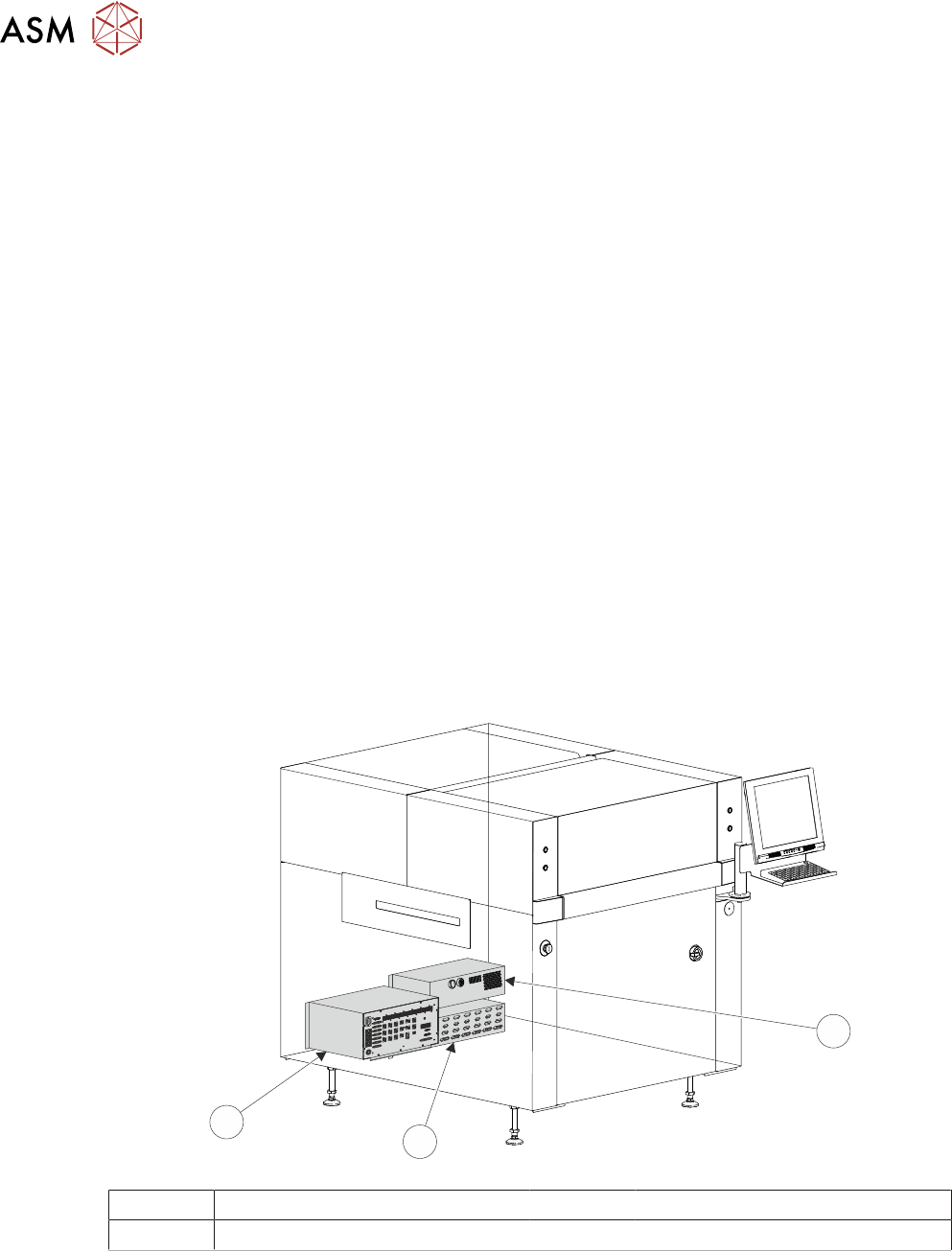
5.1.4 Printer PC Module
The machine PC enclosure is the master controller of the machine. Issuing sequential control com-
mands to slave systems via the machine control enclosure, the PC analyses the feedback signals
and issues further commands to ensure the correct operation and safety of the machine.
1
2
3
1 Machine PC Enclosure 3 Machine Power Supply Enclosure
2 Machine Control Enclosure
5 MACHINE OVERVIEW
5.1 MODULE OVERVIEWS
TECHNICAL REFERENCE MANUAL Vol 1 E By DEK 04/2019 51
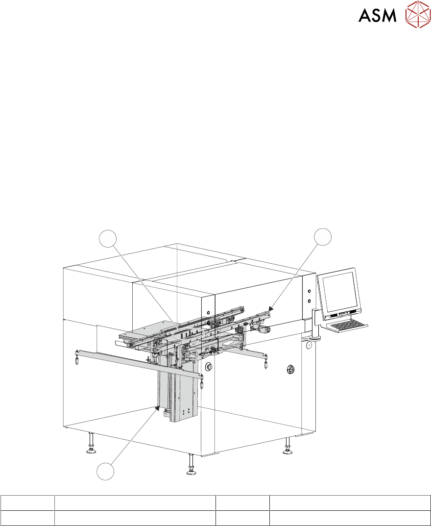
5.1.5 Rising Table Module
The rising table module provides a stable base for the board support tooling and positions the
transport rails at various heights during the print cycle.
5.1.6 Board Support Tooling Module
The role of the board support tooling is to support the board during the print stroke, to prevent print
distortion caused by flexing of the board as a result of the downward pressure of the squeegees.
Several different types of board support tooling are available to suit a variety of surface mount pro-
cess requirements.
5.1.7 Transport Rails Module
The transport rails system is a programmable width conveyor system, utilized to transport the
board through the machine and to secure the board during the print stroke. The rail system height
is positioned by the rising table, during the print cycle.
3
1
2
1 Transport Rails Module 3 Board Support Tooling Module
2 Rising Table Module