03217917-01-01E By DEK Technical Reference Manual Vol 1_enPDFA.pdf - 第284页
17 CAMERA SYSTEM MODULE 17.5 CALIBRATIONS AND CHECKS 284 TECHNICAL REFERENCE MANUAL Vol 1 E By DEK 04/2019 ► Select Continue . ► Select Back . ► Select Maintenance . ► Select Machine Setup . ► Select Basics . ► Select Bo…
17 CAMERA SYSTEM MODULE
17.5 CALIBRATIONS AND CHECKS
TECHNICAL REFERENCE MANUAL Vol 1 E By DEK 04/2019 283
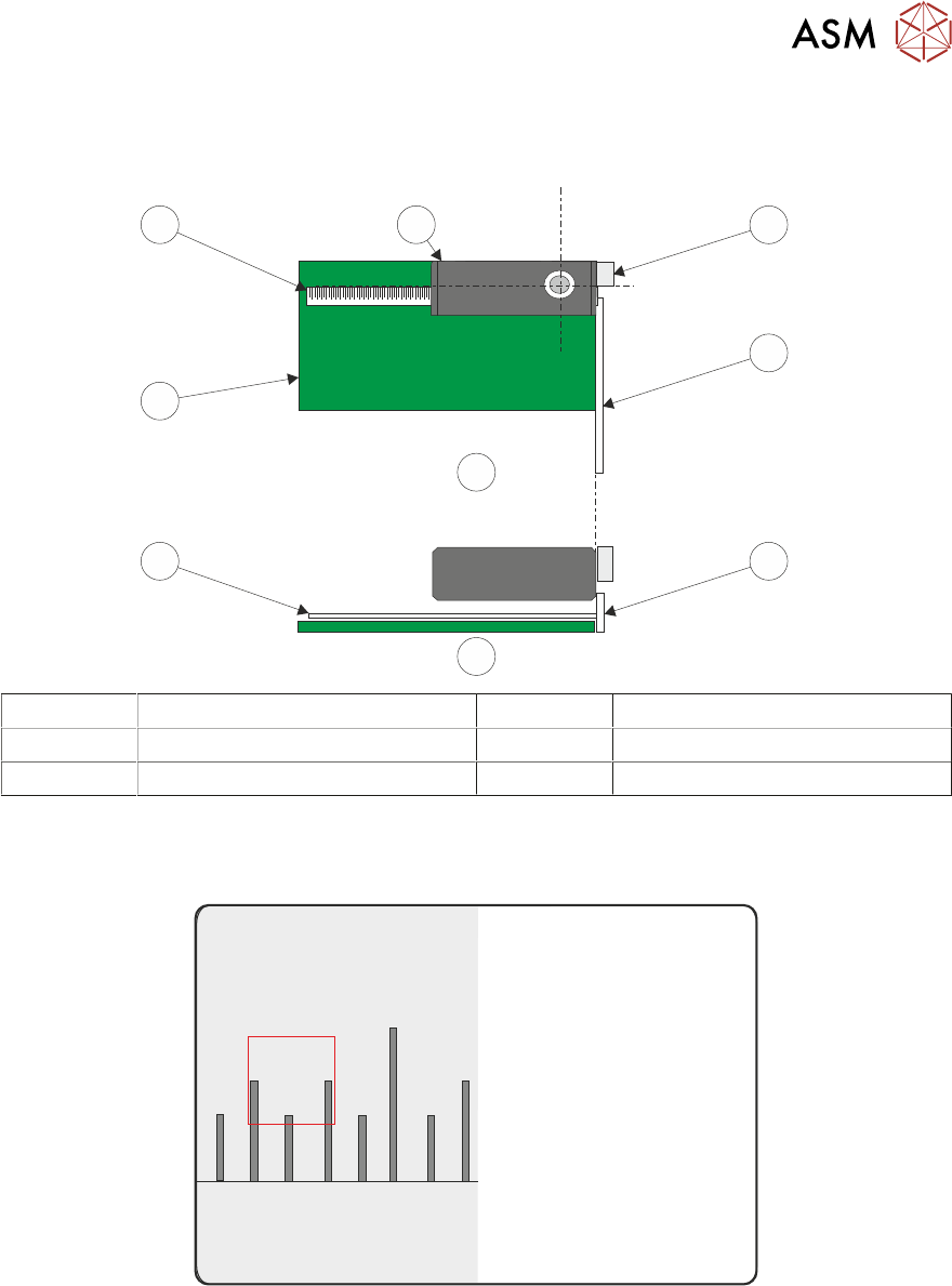
► Place a non-magnetic rule flat against the board edge and slide a second rule so that it abuts
it and comes within the camera field of view.
1
2
2
B
A
2
3
2
4
A Plan View 2 Metric Ruler
B Side View 3 Board
1 Camera Board Stop 4 Camera
► On the vision monitor, record the distance from the board edge to the approximate centre of
the square (figure below refers). This value is the Board Stop X Offset and should be
-43.5mm ±0.5mm.
45
43 4644
NOTE
The numerals on the rule may not be directly in the field of view, move the rule until the numerals
are visible in the vision window. Lay the rule flat on the board, do not lift or angle it as this can dis-
tort the measurement. As the board stop is before the camera the distance is recorded as a minus
reading.
► Remove the rule from the machine.
► Close the printhead cover.
► Press the System button.
► Select Exit.
► During Initialisation, remove the board from the transport rails when prompted.

17 CAMERA SYSTEM MODULE
17.5 CALIBRATIONS AND CHECKS
284 TECHNICAL REFERENCE MANUAL Vol 1 E By DEK 04/2019
► Select Continue.
► Select Back.
► Select Maintenance.
► Select Machine Setup.
► Select Basics.
► Select Board Stop X Offset.
► Enter the dimension recorded earlier (should be -43.5mm ±0.5mm).
► Select Accept.
► Select Back.
► Select Back.
► Select Back.
17.5.2 Vision System Calibration
For the vision alignment to function accurately a full system calibration is required. This should be
carried out by the maintenance personnel at the required period.
The calibration of the vision system is carried out in two stages using a calibration stencil (Part No.
134764) and a calibration board (Part No. 134765).
The first stage, Calibrate Vision, details the calibration of X, Y and Theta.
Calibrate Video X, Y calculates the stencil movement in millimetres to vision system pixels. This is
achieved by looking up at the calibration stencil fiducials and moving the stencil in the X and Y dir-
ections by a fixed amount, for each of the 25 fiducials.
The movements are calculated for each fiducial and the mean taken. This average stencil move-
ment is recorded and used as part of the calibration data.
Calibrate Theta calibrates the stencil theta movement. The camera selects three stencil fiducials
and the stencil moves in theta (using the two X axes and implementing +2mm in X rear and -2mm
in X forward to achieve the theta movement). The movements are calculated for each fiducial and
the average taken. The data is recorded and the calibration is complete.
The second stage, Calibrate Offset is to compensate for any optical discrepancies of the telecentric
camera between viewing up and down. This is achieved by printing the calibration stencil and
measuring the differences between the centroid of the stencil fiducials and the centroid of the prin-
ted fiducials. The average of these differences are calculated, recorded and used as part of the
calibration data.
17.5.2.1 Calibration Procedure
NOTE
The vision height adjustment must be carried out prior to calibrating the vision system.
The calibration sequence is as follows:
●
Stage 1 - Calibrate Vision
●
Stage 2 - Calibrate Offset
17.5.2.2 Stage 1 - Calibrate Vision
NOTE
ASM recommends that the calibration board and stencil are cleaned with Isopropyl Alcohol (IPA)
impregnated lint free wipe prior to calibrating vision or offset.
► Select Maintenance.
► Select Machine Setup.
► Ensure that the Screen Size parameter is set to 265.
► Select Back.
► Select Back.
► Select Setup Product.
► Select Load Product.
17 CAMERA SYSTEM MODULE
17.5 CALIBRATIONS AND CHECKS
TECHNICAL REFERENCE MANUAL Vol 1 E By DEK 04/2019 285
► Select Calibra.
► Select Load.
► Select Back.
► Select Back.
► Select Open Cover Commands.
► Select Carriage To Rear.
► Select Unload Screen.
► Open the printhead cover.
► Remove the stencil.
► Equally space 25 tooling pins on the table.
► Fit the calibration stencil
► Close the printhead cover.
► Press the System button.
► Select Load Screen.
► Select Back.
► Select Setup Product.
► Select Fiducials.
► Select Global Settings.
► Ensure that Alignment Mode is set to 2 Fiducial.
► Select Back.
► Select Back.
► Select Back.
► Select Maintenance.
► Select Calibrations.
► Select Classic Calibrations.
► Select Vision.
► Select Screen OK.
► Select Use Screen, if displayed.
► Load the calibration board on to the input conveyor.
► Select Auto Board, the board moves to the board stop position.
► Select Step, the board is clamped and the board stop retracts.
► Select Step, the camera moves to the first stencil fiducial and the squeegee moves to dwell
height.
► Using a combination of the Incr. and Decr. and Next. or Previous. buttons and viewing the
right hand side of the vision monitor, position the stencil fiducial so that it is placed centrally
within the box displayed.
► Select Step, the camera moves to the second stencil fiducial. Position the fiducial centrally
within the box as previously described.
► Select Step, the camera moves to the third stencil fiducial. Position the fiducial centrally within
the box as previously described.
► Select Step, the camera moves to the fourth stencil fiducial. Position the fiducial centrally
within the box as previously described.