03217917-01-01E By DEK Technical Reference Manual Vol 1_enPDFA.pdf - 第177页
13 ADJUSTABLE WIDTH STENCIL MOUNT 13.1 OVERVIEW TECHNICAL REFERENCE MANUAL Vol 1 E By DEK 04/2019 177 13 ADJUSTABLE WIDTH STENCIL MOUNT 13.1 OVERVIEW 1 3 2 4 5 6 7 8 9 15 10 1 1 12 13 14 1 Roller Counter Plate (4 positio…

12 MACHINED C CHASE MODULE
12.4 CALIBRATIONS
176 TECHNICAL REFERENCE MANUAL Vol 1 E By DEK 04/2019
12.4 CALIBRATIONS
12.4.1 Chase to Table Level
Chase to Table Level setting is factory set and no attempt should be made to make adjustment. If
the Chase to Table Level reading is suspected, a coplanarity procedure must be carried out before
commencing printing. Please contact your local customer support office for more detail.
13 ADJUSTABLE WIDTH STENCIL MOUNT
13.1 OVERVIEW
TECHNICAL REFERENCE MANUAL Vol 1 E By DEK 04/2019 177
13
ADJUSTABLE WIDTH STENCIL MOUNT
13.1 OVERVIEW
1
3
2
4
5
6
7
8
9
15
10
11
12
13
14
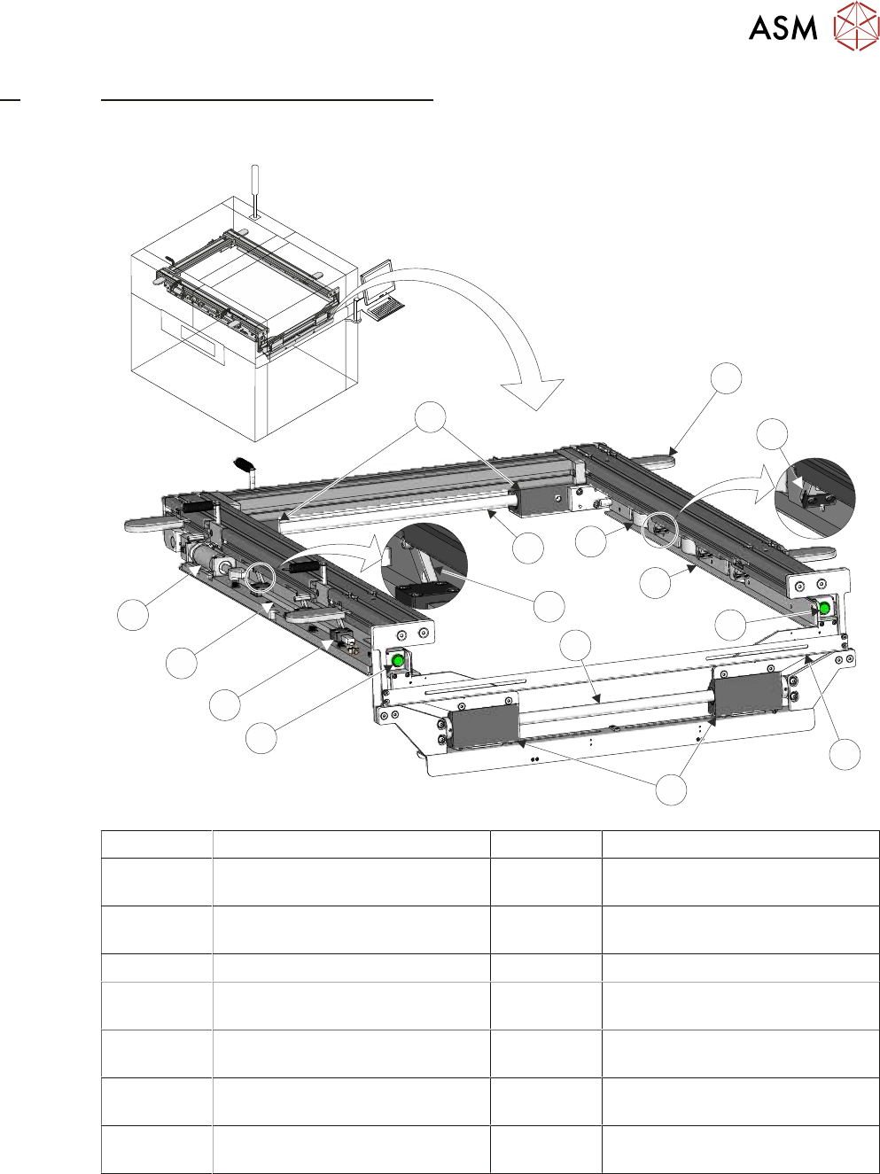
1 Roller Counter Plate (4 positions) 9 Stencil Clamp Lever (6 positions)
2 Stencil Location Leaf Spring
(3 positions)
10 Left Hand Chase Rail Release
Button
3 Stencil Clamp (6 positions) 11 Stencil Clamp Lever Actuator Bar
Guide (6 positions)
4 Stencil Support Plate (2 positions) 12 Stencil Clamp Lever Actuator Bar
5 Right Hand Chase Rail Release
Button
13 Stencil Clamp Pneumatic
Cylinder (2 positions)
6 Stencil Width Measuring Scale 14 Width Locking Mechanisms
(Rear)
7 Width Locking Mechanisms
(Front)
15 Chase Rail Assembly Guide Shaft
(Rear)
8 Chase Rail Assembly Guide Shaft
(Front)
The AWSM module provides a receptacle for the stencil, where it is clamped in the correct position
for printing. The module width can be easily adjusted to accommodate stencils from 29 inches
through to 12 inches square with 250mm belt support plates, or 29 inches through to 23 inches
square with 500mm belt support plates.
NOTE
The height of the stencil must exceed 19mm to be clamped firmly.
The stencil image can be front or centre justified.
13 ADJUSTABLE WIDTH STENCIL MOUNT
13.1 OVERVIEW
178 TECHNICAL REFERENCE MANUAL Vol 1 E By DEK 04/2019
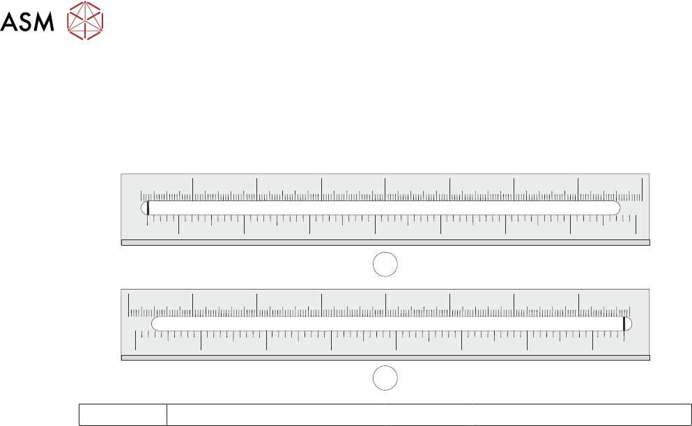
The pneumatic push buttons located on the inside of the front left and right hand web assemblies
are operated, releasing all four web assemblies on the front and rear rail assembly guide shafts.
Releasing the web assemblies allows the user to adjust the position of the left and right hand chase
rail assemblies, to accommodate for the appropriate size stencil using the stencil width measuring
scale.
700 650 600 550 450 350400500
29" 28" 26" 24" 22" 20" 18" 16" 14"
700650600550450350 400 500
29"
28"
26"
24"22"
20"
18"
16"
14"
1
2
1 Left Hand Scale 2 Right Hand Scale
The stencil is loaded from the front of the printer and slid into the printer along the top of stencil
support plates. Three stencil location leaf springs (located in the right hand chase rail assembly)
ensures the stencil is pushed against the stencil guide strips on the left hand chase rail assembly.
The stencil is clamped in the AWSM using pneumatically activated flaps that clamp the stencil to
the stencil support plates.
The AWSM is a floating assembly mounted on a bearing set and is aligned to the correct printing
position using three actuators. Once aligned, the AWSM is pneumatically clamped to the left and
right printhead assemblies (for further details refer to 14 "SCREEN ALIGNMENT MOD-
ULE" [}185]).