03217917-01-01E By DEK Technical Reference Manual Vol 1_enPDFA.pdf - 第210页
15 BOARD STOP 15.6 ADJUSTMENTS AND SETTINGS 210 TECHNICAL REFERENCE MANUAL Vol 1 E By DEK 04/2019 15.6.5 Camera to Remote Board Stop - RHS Configuration W ARNING BOARD CLAMPS. EXTREME CARE MUST BE EXERCISED WHEN WORKING …
15 BOARD STOP
15.6 ADJUSTMENTS AND SETTINGS
TECHNICAL REFERENCE MANUAL Vol 1 E By DEK 04/2019 209
7
6
5
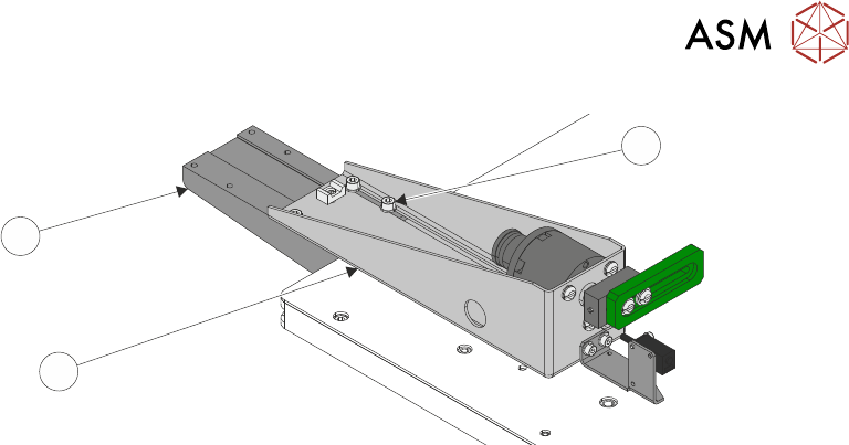
► Using the appropriate slots, loosely secure the remote board stop assembly (5) to the base
clamp (6), using the four M5 cap head screws (7).
► Connect plug 8PL05 to socket 8SK05L.
► Connect the pipe marked Remote/B/Stop L1 to the in-line connector on the pipe marked 1 on
the remote board stop.
► Connect the pipe marked Remote/B/Stop L2 to the in-line connector on the pipe marked 2 on
the remote board stop.
► Refit the left hand side safety cover.
► Reconnect the mains air quick release connection to the machine.
► Switch the mains isolator to ON.
► Press the Start button.
► When prompted select Diagnostics.
► When prompted press the System button.
► Carry out 15.6.3 "Setting the Remote Board Stop" [}203].

15 BOARD STOP
15.6 ADJUSTMENTS AND SETTINGS
210 TECHNICAL REFERENCE MANUAL Vol 1 E By DEK 04/2019
15.6.5 Camera to Remote Board Stop - RHS Configuration
WARNING
BOARD CLAMPS. EXTREME CARE MUST BE EXERCISED WHEN WORKING IN
THE TOOLING AREA OF THE MACHINE TO AVOID INJURY. THE FOILS ON THE
FRONT AND REAR BOARD CLAMPS ARE VERY SHARP.
WARNING
COMPRESSED AIR. COMPRESSED AIR SHOULD NEVER IMPINGE UPON THE
BODY. PORTS, PIPES, ETC MUST NEVER BE BLOCKED BY HAND. BEFORE
CONNECTING OR DISCONNECTING ANY PNEUMATIC COMPONENTS, ENSURE
THE COMPRESSED AIR SUPPLY HAS BEEN DISSIPATED AND DISCONNECTED
FROM THE MACHINE.
This procedure details the changes required to convert from using the camera mounted board stop
to the remote board stop mounted on the right hand side of the rising table.
15.6.5.1 Preparation
► Select Open Cover Commands.
► Select Carriage To Rear.
► Select Unload Screen.
► Open the front printhead cover.
► Remove the screen from the machine.
► Close the front printhead cover.
► Press the System button.
► Select Back.
► Select Maintenance.
► Select Machine Setup.
► Select Options.
► Select Remote Board Stop.
► Select Fitted.
► Select Accept.
► Select Back.
► Select Back.
► Select Back.
► Select Setup Product.
► Select Load Product.
► Select the product file to be used with the remote board stop.
NOTE
The selected product file must have a board width of 130mm or greater.
► Select Load.
► Select Back.
► Select Back.
15 BOARD STOP
15.6 ADJUSTMENTS AND SETTINGS
TECHNICAL REFERENCE MANUAL Vol 1 E By DEK 04/2019 211
15.6.5.2 External Services
► Select Shut Down.
► Select Continue.
► Switch the mains isolator to OFF.
► Disconnect the quick release mains air connection at the rear the machine.
► Remove the machine rear cover.
► Remove the right hand side safety cover.
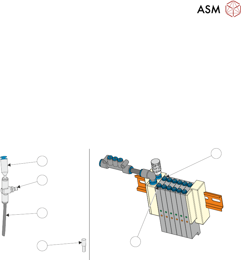
► At the board stop solenoid (16SOL14), on the pneumatic manifold at the rear of the machine:
► Remove the pipe marked Board Stop from the front port (A) (2).
► If an in-line flow controller is not already connected to the rear port (B) (1), remove the exist-
ing blanking plug (3) from the rear port (B) (1) and fit the in-line flow controller (5), via the
50mm x 4mm pipe (4) (both supplied with the remote board stop) to the rear port (B) (1). The
in-line flow controller (5) should have a self-seal connector (6) at its open end.
1
2
3
4
5
6
► Fit the pipe marked Remote/B/Stop Up - RH to the front port (A) (2).
► Fit the pipe marked Remote/B/Stop Down - RH to the in-line flow controller, self-seal con-
nector (6) fitted to the rear port (B) (1).
► Behind the front cover, mounted on the machine frame next to the 4 port USB hub:
1. Remove plug BPL6 from socket BSK6.
2. Connect plug BPL6A to socket BSK6.
► Fit the rear cover.