03217917-01-01E By DEK Technical Reference Manual Vol 1_enPDFA.pdf - 第68页
6 POWER SUPPLY M37 6.3 M37 POWER SUPPLY ENCLOSURE 68 TECHNICAL REFERENCE MANUAL Vol 1 E By DEK 04/2019 6.3.2 PSU Monitor Board The board monitors the voltages at circuit breakers CB1 to CB31 on the power distribution PCB…

6 POWER SUPPLY M37
6.3 M37 POWER SUPPLY ENCLOSURE
TECHNICAL REFERENCE MANUAL Vol 1 E By DEK 04/2019 67
6.3.1.1 E Stop Loop
WARNING
E STOP CIRCUIT. THE E STOP CIRCUIT ONLY ISOLATES THE DC SUPPLIES
TO THE MOTORS. LETHAL VOLTAGES ARE STILL PRESENT WITHIN THE
MACHINE AFTER THE E STOP HAS BEEN ACTIVATED.
The emergency stop loop consists of a series circuit connecting the E Stop blanking plug, the E
Stop button, the front cover interlock and the rear cover interlock/interlock blanking plug. The E
Stop loop supply (software E Stop) from the NextMove interface card passes through the E Stop
loop to the solenoid of the E Stop relay. Once energised the E Stop relay feeds 24V US from the
PSU to the solenoids of contactors Con 1, Con 2 and Con 3. Once energized contactor Con 1
feeds 24V SW via contactor Con 3 to provide stepper motor drive. Contactor Con 2 feeds +42V dc
or +48V dc via contactor Con 3 to provide servo motor power.
If any component in the loop becomes open circuit or if the E Stop loop supply drops to 0V, the E
Stop relay PNOZ X2 de-energises. Contactors Con 1, Con 2 and Con 3 de-energise, this ensures
the immediate shut down of all motors.
On E Stop activation, the machine monitor displays the Restore Power window. The recovery
method is to remove the E Stop condition and press the System button.
The M37 power supply enclosure has been designed to be machine generic, because of this,
blanking plugs are fitted where interlocks are not required.
6.3.1.2 Two-Handed Relay
With the printhead cover open the machine sees this as an E Stop condition and motor power is
not available. The two-handed relay enables functions such as priming paper and priming solvent
to be carried out with the printhead cover open. The operator selects the required function on the
MMI prior to opening the printhead cover. Once selected both jog buttons are used to perform the
task.
Provided the two jog buttons are pressed within 0.5 seconds of each other, the two-handed safety
relay internal control circuit allows the safety relay contacts to switch. Contactors Con 1 and Con 3
activate to enable the 24V SW supply. As contactor Con 2 does not become energized, power is
not available for servo motor drive.
The 24V SW power is enabled whilst the jog buttons are held on. The software, having being noti-
fied that a prime paper or prime solvent function has been selected, provides drive to the relevant
circuit.
6.3.1.3 System Switch
Provided the E Stop loop is intact, the E Stop loop supply is at 24V and is available at the E Stop
relay solenoid. System power is controlled by the system switch which is connected to the reset
terminals of the E Stop relay control circuit. Internal auxiliary contacts CON1, CON2 and CON3 are
wired in series with the system switches, this allows the E Stop relay to monitor the contactors to
ensure that they have not welded shut.
By pressing and releasing the system switch, the relay control circuit enables the activation of the
24V switching contacts and power is available to contactors Con 1, Con 2 and Con 3. Contactor
Con 2, via contactor Con 3, enables system power to be available and this is signalled to the con-
trol enclosure with the switching on of Q1. With the 24V SW supply now available, the system lamp
comes on and stays on even though the system switch has been released. Contactor Con 2, via
contactor Con 3, also enables the 42V dc or 48V dc servomotor supply.
6 POWER SUPPLY M37
6.3 M37 POWER SUPPLY ENCLOSURE
68 TECHNICAL REFERENCE MANUAL Vol 1 E By DEK 04/2019
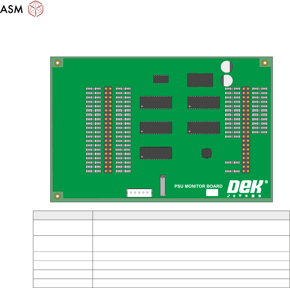
6.3.2 PSU Monitor Board
The board monitors the voltages at circuit breakers CB1 to CB31 on the power distribution PCB
and sends a data stream via the USB port M37SK30 to the machine PC.
181507 ISSUE
Voltage Where Used
+24V US NextMove Interface, MIU, Camera Lighting, Stepper Logic, Machine Fans,
I/O Node Power, Grid-Lok Tooling, EuroFlex and Servo Motor Logic
+24V SW NextMove Interface, MIU, Belt Motors, I/O Node Power and Grid-Lok
Tooling
+5.5V NextMove ES, USB Hub
+12V I/O Node Power and Grid-Lok Tooling
-12V NextMove ES
+42V/+48V Servo Motor Supply
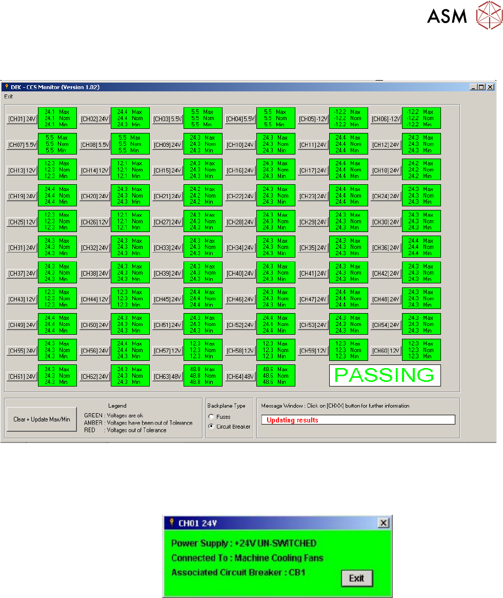
A separate application is used to display the voltage readings on the machine monitor, to access
this window carry out the following:
► Switch ON and initialise the machine.
► On the keyboard, press the Windows key to access the taskbar.
6 POWER SUPPLY M37
6.3 M37 POWER SUPPLY ENCLOSURE
TECHNICAL REFERENCE MANUAL Vol 1 E By DEK 04/2019 69
► On the taskbar, select Start, Programs, DEK Power Monitor. The following window is dis-
played:
NOTE
Ensure that the Circuit Breaker radio button is checked in Backplane Type.
Clicking on the channel ID button, i.e. (CH01) 24V, opens a further information window, an exam-
ple of which is shown below: