03217917-01-01E By DEK Technical Reference Manual Vol 1_enPDFA.pdf - 第220页
15 BOARD STOP 15.6 ADJUSTMENTS AND SETTINGS 220 TECHNICAL REFERENCE MANUAL Vol 1 E By DEK 04/2019 ► Select Back . ► Select Back . 15.6.7.2 External Services ► Select Shut Down . ► Select Continue . ► Switch the mains iso…
15 BOARD STOP
15.6 ADJUSTMENTS AND SETTINGS
TECHNICAL REFERENCE MANUAL Vol 1 E By DEK 04/2019 219
15.6.7 Remote Board Stop - RHS to LHS Configuration
WARNING
BOARD CLAMPS. EXTREME CARE MUST BE EXERCISED WHEN WORKING IN
THE TOOLING AREA OF THE MACHINE TO AVOID INJURY. THE FOILS ON THE
FRONT AND REAR BOARD CLAMPS ARE VERY SHARP.
WARNING
COMPRESSED AIR. COMPRESSED AIR SHOULD NEVER IMPINGE UPON THE
BODY. PORTS, PIPES, ETC MUST NEVER BE BLOCKED BY HAND. BEFORE
CONNECTING OR DISCONNECTING ANY PNEUMATIC COMPONENTS, ENSURE
THE COMPRESSED AIR SUPPLY HAS BEEN DISSIPATED AND DISCONNECTED
FROM THE MACHINE.
This procedure details the changes required to convert the machine configuration from a right hand
mounted remote board stop to a left hand mounted remote board stop.
15.6.7.1 Preparation
► Select Open Cover Commands.
► Select Carriage To Rear.
► Select Unload Screen.
► Open the front printhead cover.
► Remove the screen from the machine.
► Remove the left and right hand side safety covers.
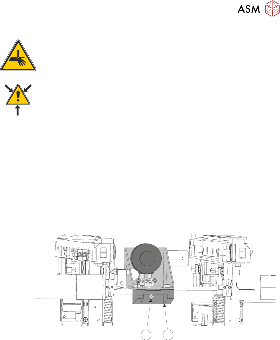
► Loosen the securing screw (2) from the underside of the base clamp (1), using a 4mm Allen
key.
12
► Slide the remote board stop to the front of the machine, until it abuts the front rail.
► Close the front printhead cover.
► Press the System button.
► Select Back.
► Select Setup Product.
► Select Load Product.
► Select the product file to be used with the remote board stop.
NOTE
The selected product file must have a board width of 130mm or greater.
► Select Load.
15 BOARD STOP
15.6 ADJUSTMENTS AND SETTINGS
220 TECHNICAL REFERENCE MANUAL Vol 1 E By DEK 04/2019
► Select Back.
► Select Back.
15.6.7.2 External Services
► Select Shut Down.
► Select Continue.
► Switch the mains isolator to OFF.
► Disconnect the quick release mains air connection at the rear the machine.
► Remove the machine rear cover.
► At the board stop solenoid (16SOL14), on the pneumatic manifold at the rear of the machine:
► Remove the pipe marked Remote/B/Stop Up - RH from the front port (A).
► Remove the pipe marked Remote/B/Stop Down - RH from the in-line flow controller, self-seal
connector fitted to the rear port (B).
► Fit the pipe marked Remote/B/Stop Up - LH to the front port (A).
► Fit the pipe marked Remote/B/Stop Down - LH to the in-line flow controller, self-seal con-
nector fitted to the rear port (B).
► Fit the rear cover.
15.6.7.3 Fitting the Remote Board Stop
► Open the front printhead cover.
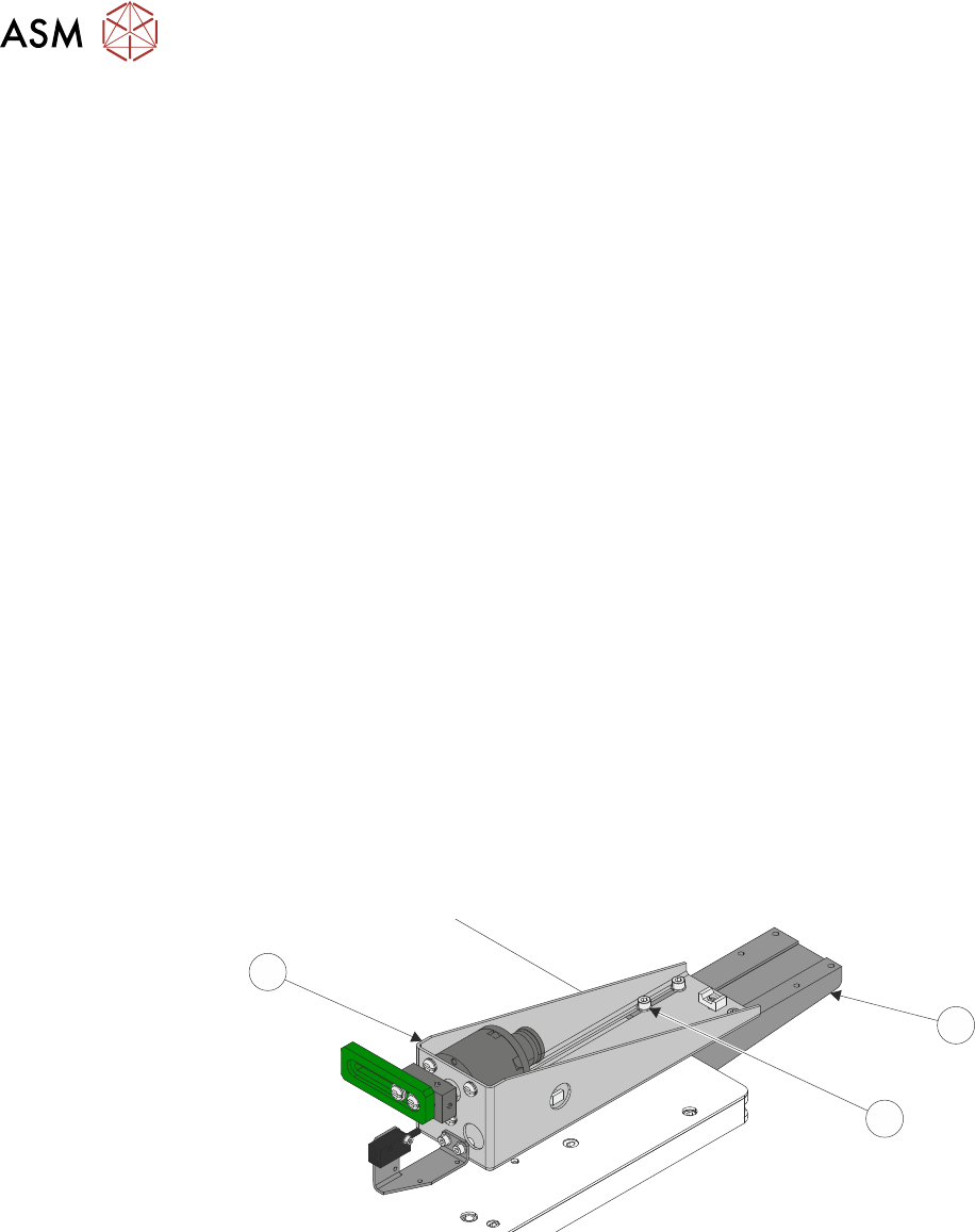
► At the remote board stop assembly:
●
Disconnect 8PL05 from 8SK05R.
●
Disconnect the pipe from the in-line connector on the pipe marked 1.
●
Disconnect the pipe from the in-line connector on the pipe marked 2.
► Remove the four M5 cap head screws and washers (2) from the board stop assembly (3) us-
ing a 5mm Allen key.
1
2
3
► Remove the board stop assembly (3) from the machine.
15 BOARD STOP
15.6 ADJUSTMENTS AND SETTINGS
TECHNICAL REFERENCE MANUAL Vol 1 E By DEK 04/2019 221
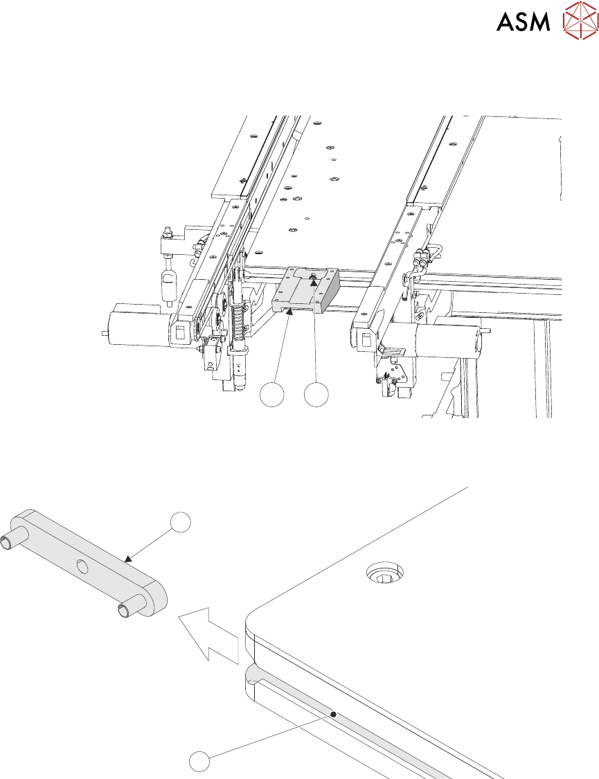
► Loosen the base clamp securing screw (4) sufficiently, using a 4mm Allen key, to remove the
base clamp (1) from the machine.
1
4
► Remove the base clamp locating nut (5) from the attachment slot (6) on the right hand side of
the rising table.
6
5