03217917-01-01E By DEK Technical Reference Manual Vol 1_enPDFA.pdf - 第285页
17 CAMERA SYSTEM MODULE 17.5 CALIBRATIONS AND CHECKS TECHNICAL REFERENCE MANUAL Vol 1 E By DEK 04/2019 285 ► Select Calibra . ► Select Load . ► Select Back . ► Select Back . ► Select Open Cover Commands . ► Select Carria…

17 CAMERA SYSTEM MODULE
17.5 CALIBRATIONS AND CHECKS
284 TECHNICAL REFERENCE MANUAL Vol 1 E By DEK 04/2019
► Select Continue.
► Select Back.
► Select Maintenance.
► Select Machine Setup.
► Select Basics.
► Select Board Stop X Offset.
► Enter the dimension recorded earlier (should be -43.5mm ±0.5mm).
► Select Accept.
► Select Back.
► Select Back.
► Select Back.
17.5.2 Vision System Calibration
For the vision alignment to function accurately a full system calibration is required. This should be
carried out by the maintenance personnel at the required period.
The calibration of the vision system is carried out in two stages using a calibration stencil (Part No.
134764) and a calibration board (Part No. 134765).
The first stage, Calibrate Vision, details the calibration of X, Y and Theta.
Calibrate Video X, Y calculates the stencil movement in millimetres to vision system pixels. This is
achieved by looking up at the calibration stencil fiducials and moving the stencil in the X and Y dir-
ections by a fixed amount, for each of the 25 fiducials.
The movements are calculated for each fiducial and the mean taken. This average stencil move-
ment is recorded and used as part of the calibration data.
Calibrate Theta calibrates the stencil theta movement. The camera selects three stencil fiducials
and the stencil moves in theta (using the two X axes and implementing +2mm in X rear and -2mm
in X forward to achieve the theta movement). The movements are calculated for each fiducial and
the average taken. The data is recorded and the calibration is complete.
The second stage, Calibrate Offset is to compensate for any optical discrepancies of the telecentric
camera between viewing up and down. This is achieved by printing the calibration stencil and
measuring the differences between the centroid of the stencil fiducials and the centroid of the prin-
ted fiducials. The average of these differences are calculated, recorded and used as part of the
calibration data.
17.5.2.1 Calibration Procedure
NOTE
The vision height adjustment must be carried out prior to calibrating the vision system.
The calibration sequence is as follows:
●
Stage 1 - Calibrate Vision
●
Stage 2 - Calibrate Offset
17.5.2.2 Stage 1 - Calibrate Vision
NOTE
ASM recommends that the calibration board and stencil are cleaned with Isopropyl Alcohol (IPA)
impregnated lint free wipe prior to calibrating vision or offset.
► Select Maintenance.
► Select Machine Setup.
► Ensure that the Screen Size parameter is set to 265.
► Select Back.
► Select Back.
► Select Setup Product.
► Select Load Product.

17 CAMERA SYSTEM MODULE
17.5 CALIBRATIONS AND CHECKS
TECHNICAL REFERENCE MANUAL Vol 1 E By DEK 04/2019 285
► Select Calibra.
► Select Load.
► Select Back.
► Select Back.
► Select Open Cover Commands.
► Select Carriage To Rear.
► Select Unload Screen.
► Open the printhead cover.
► Remove the stencil.
► Equally space 25 tooling pins on the table.
► Fit the calibration stencil
► Close the printhead cover.
► Press the System button.
► Select Load Screen.
► Select Back.
► Select Setup Product.
► Select Fiducials.
► Select Global Settings.
► Ensure that Alignment Mode is set to 2 Fiducial.
► Select Back.
► Select Back.
► Select Back.
► Select Maintenance.
► Select Calibrations.
► Select Classic Calibrations.
► Select Vision.
► Select Screen OK.
► Select Use Screen, if displayed.
► Load the calibration board on to the input conveyor.
► Select Auto Board, the board moves to the board stop position.
► Select Step, the board is clamped and the board stop retracts.
► Select Step, the camera moves to the first stencil fiducial and the squeegee moves to dwell
height.
► Using a combination of the Incr. and Decr. and Next. or Previous. buttons and viewing the
right hand side of the vision monitor, position the stencil fiducial so that it is placed centrally
within the box displayed.
► Select Step, the camera moves to the second stencil fiducial. Position the fiducial centrally
within the box as previously described.
► Select Step, the camera moves to the third stencil fiducial. Position the fiducial centrally within
the box as previously described.
► Select Step, the camera moves to the fourth stencil fiducial. Position the fiducial centrally
within the box as previously described.
17 CAMERA SYSTEM MODULE
17.5 CALIBRATIONS AND CHECKS
286 TECHNICAL REFERENCE MANUAL Vol 1 E By DEK 04/2019
► Select Step. The control screen displays the following message, ‘Printer configurationdata
file saved’.
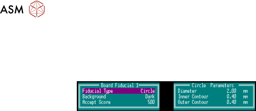
► Select Brd. Fid. Setup and set up the board fiducial on the left side of the vision monitor. To
change the fiducial select Type, Background and Accept Score.
NOTE
Ensure the Background is set to Dark and the Diameter is at 2.00mm.
► Select Learn Fiducial. Using a combination of the Incr. or Decr. and the Next or Previous
buttons set up Fiducial 1 position in X or Y, and for a Circle:
Diameter, Inner Contour and Outer Contour.
► Select Learn Fiducial.
► Select Exit.
► Select Locate Fiducial.
NOTE
The Acceptance Score should be over 500. If not repeat.
► Select Exit.
► Select Scn. Fid. Setup. Using a combination of the Incr. or Decr. and the Next or Previous
buttons set up the stencil fiducial on the right side of the vision monitor set the background to
Light and the Diameter to 1.00mm.
► Select Learn Fiducial.
► Using a combination of the Incr. or Decr. and the Next or Previous buttons set up the stencil
fiducial on the right side of the vision monitor.
► Select Learn Fiducial.
► Select Exit.
► Select Locate Fiducial.
NOTE
1. If the board fiducial is not visible and cannot be brought into view by small adjustments, in the
camera axis calibration, check the reference position on the front rail. If the front rail reference
position is incorrect, adjust its position. If the reference position is correct contact Customer
Support Group for assistance.
2. If for any reason the camera cannot locate the board or stencil fiducial, select Fiducial Setup
and relearn the fiducial, (refer to 17.6 "APPENDIX A - VISION SYSTEM SETUP" [}289]for
details on setting up the fiducial recognition strategy).
3. Select Exit the sequence continues and should not have any detrimental effect on the cali-
bration.
► Select Exit.
► Select Exit.
► Select Single, the camera locates all 25 fiducials.
► Select Continue.
► Select Single, the camera locates 50 fiducials.
► Select Exit.
► Remove the board from the transport rails by hand.
NOTE
Do not select Auto Board.