03217917-01-01E By DEK Technical Reference Manual Vol 1_enPDFA.pdf - 第268页
17 CAMERA SYSTEM MODULE 17.3 ADJUSTMENTS AND SETTINGS 268 TECHNICAL REFERENCE MANUAL Vol 1 E By DEK 04/2019 ► Using feeler gauges (6) check that the gap between both alignment pads (8) and the belt sup- port plate (7) of…
17 CAMERA SYSTEM MODULE
17.3 ADJUSTMENTS AND SETTINGS
TECHNICAL REFERENCE MANUAL Vol 1 E By DEK 04/2019 267
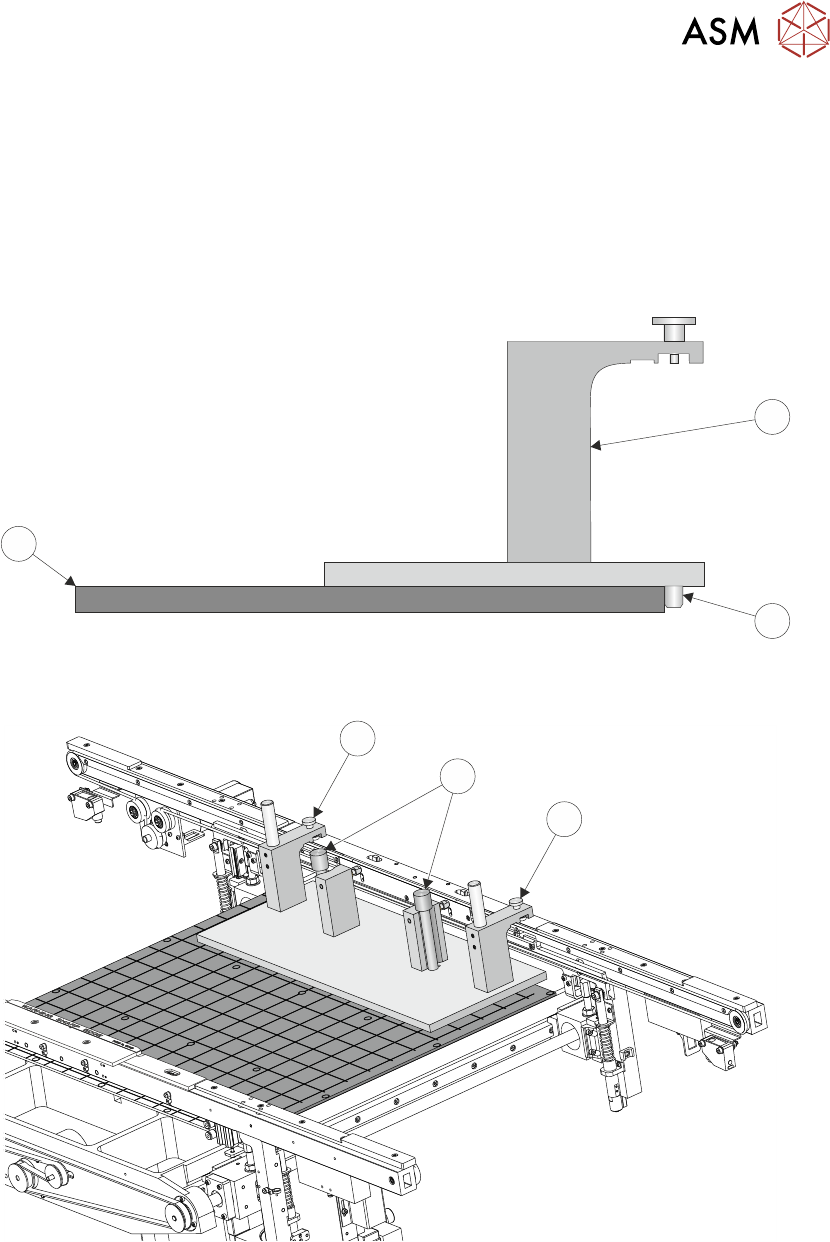
► There are two versions of the rail setting jig (Part No. 191156) and they are labelled:
●
Standard Rails (round belts)
●
Heavy Board Rails (flat belts)
► Confirm which type of rails are fitted to the machine and select the appropriate rail setting jig.
► Place the jig (1) on the manual tooling plate (3) ensuring that the location pins (2) on the un-
derside of the jig (1) are located in the holes on the manual tooling plate (3). Check there is no
gap using a 0.05mm feeler gauge.
3
1
2
► Secure the jig (1) to the front rail using the two jig to rail thumbscrews (4).
4
5
4
► Secure the jig (1) to the rising table using the two jig to table thumbscrews (5).
► Check that the location pins (2) are up against the front edge of the manual tooling plate (3)
using a 0.05mm feeler gauge.
17 CAMERA SYSTEM MODULE
17.3 ADJUSTMENTS AND SETTINGS
268 TECHNICAL REFERENCE MANUAL Vol 1 E By DEK 04/2019
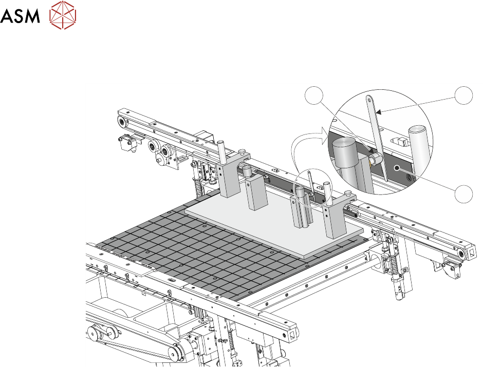
► Using feeler gauges (6) check that the gap between both alignment pads (8) and the belt sup-
port plate (7) of the front rail is 0.25mm ±0.05mm.
8 6
7
► If adjustment is necessary, refer to 16.4.5 "Front Rail Parallelism" [}243].
► Bring the camera carriage X axis support platform into contact with the camera alignment
pins.

17 CAMERA SYSTEM MODULE
17.3 ADJUSTMENTS AND SETTINGS
TECHNICAL REFERENCE MANUAL Vol 1 E By DEK 04/2019 269
A
View on A
0.25 mm
9
14
13
12
11
12
13
10
9 Camera X Axis Support Platform 12 Camera Alignment Pins
(2 positions)
10 Rising Table 13 Shim 0.25mm
11 Alignment Jig 14 Linear Bearing
► Look for a gap between the camera alignment pins and the linear bearing on the front edge of
the camera X axis support platform, if no gap exists adjustment is unnecessary. Continue
from Parallelism Complete.
► If a gap exists, carefully attempt to insert a 0.25mm shim between the alignment pin and the
linear bearing on the front edge of the camera X axis support platform. If the shim cannot be
fitted the gap is less than 0.25mm and adjustment is unnecessary. Continue from Parallelism
Complete.
► If a gap exists which is greater than 0.25mm adjustment is necessary.
► Loosen the three securing screws.