03217917-01-01E By DEK Technical Reference Manual Vol 1_enPDFA.pdf - 第61页
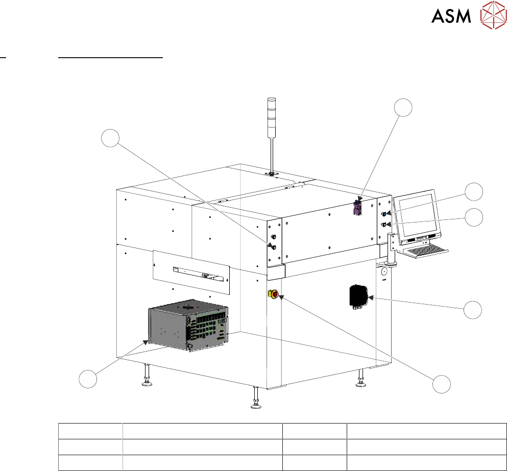
6 POWER SUPPLY M37 6.1 OVERVIEW TECHNICAL REFERENCE MANUAL Vol 1 E By DEK 04/2019 61 6 POWER SUPPLY M37 6.1 OVERVIEW 3 6 5 4 3 2 1 1 Front Printhead Cover Interlock 4 Mains Isolator Switch 2 System Button 5 E Stop Button…
5 MACHINE OVERVIEW
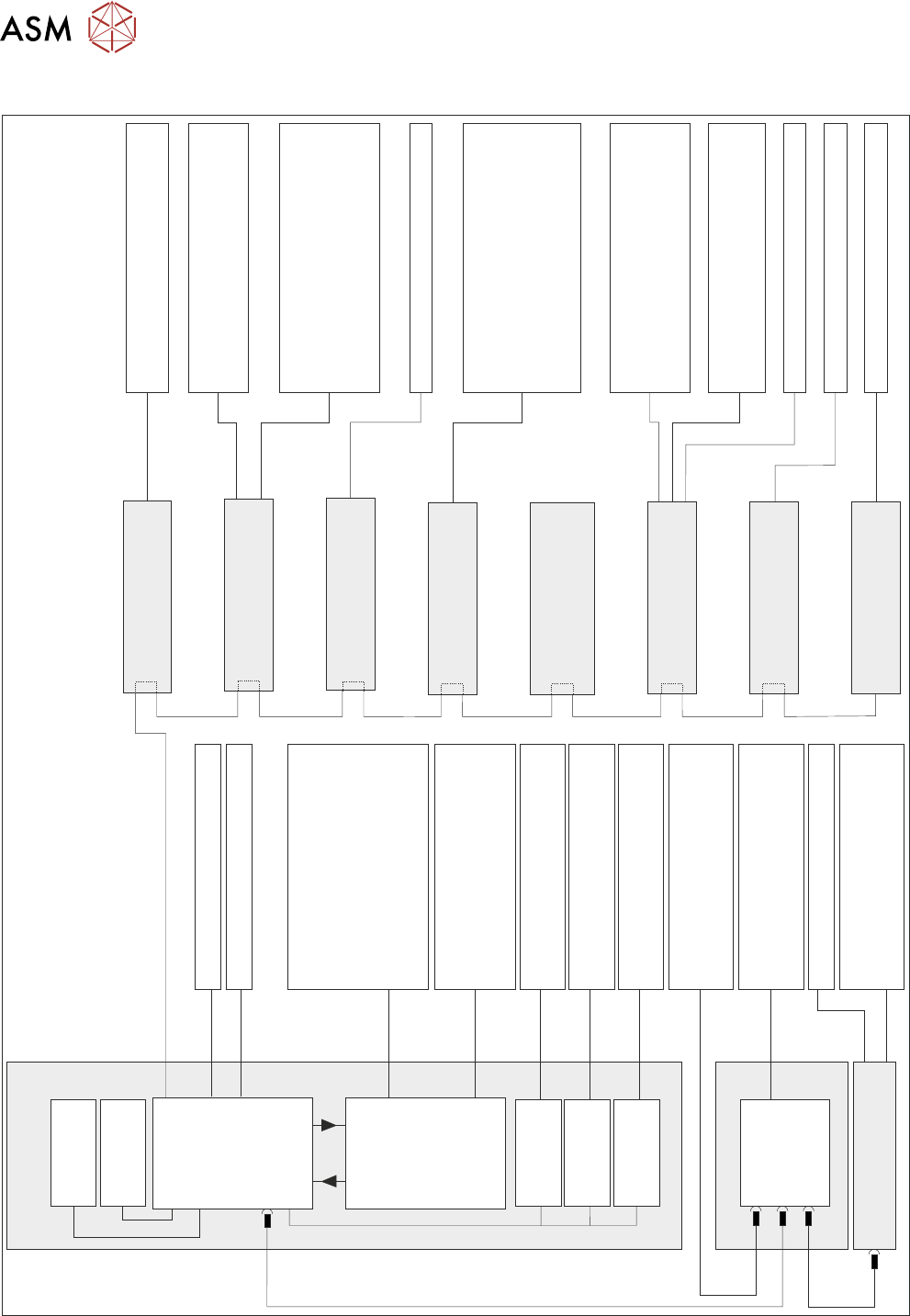
5.3 ELECTRICAL SCHEMATIC
60 TECHNICAL REFERENCE MANUAL Vol 1 E By DEK 04/2019
5.3 ELECTRICAL SCHEMATIC
X Forward Actuator
X Rear Actuator
USB
USB
USB
PC
Motherboard
M36 Machine
Control Enclosure
NextMove
Interface
Dual Stepper
Card X3
Dual Stepper
Card X2
Dual Stepper
Card X1
NextMove ES
(I/O Node 1)
I/Ps O/Ps
CAN Bus
O/Ps
O/Ps
I/Os
Front Squeegee Motor
Rear Squeegee Motor
Y Actuator
Moving Rail Motor
M37 Power
Supply Module
O/P
I/Ps
O/Ps
Camera Trigger
Transport Belt Motors
FMI
E Stop Power
I/Ps
Squeegee Home Sensors
Transport Rail Sensors
Board Stop Sensors
Jog Buttons (via M37)
Cover Interlock
FMI
Power ‘ON’ Monitor
System Switch
Jog Buttons
E Stop
MMI Touchscreen (Option)
Keyboard/Mouse
USB Flash Drive
Host Comms
DEK Interactiv
Camera System (vision)
Aout
Temperature to ECM
Ain
O/Ps
USC Solvent Level
System Lamp
Board Stop
Chase/Screen/Board Clamps
Lid Bolt
Tricolour Beacon
USC Cleaner Squeegee
Vacuum Tooling Power
Air Pressure Sensor
Lid Bolt Sensor
Screen Sensor
Vacuum Tooling Sensor
Camera Y Home
Print Carriage Home Sensor
Servo Node 8
(Camera X)
Camera X Home
USC Sensors
USC Home Clamps
USC Motors and Solvent Pump
Vacuum Power
Drip Tray Solenoid
Paste Height Laser
Screen Actuator
Servo Node 6
(Rising Table Motor)
I/O Node 3 Board
(Print Carriage)
Servo Node 7
(Print Carriage Motor)
Servo Node 7
(Print Carriage Motor)
I/O Node 2 Board
(Main Machine)
Various Rail Stepper
Nodes (see Machine
Control chapter)
Servo Node 9
(Camera Y)
I/O Node 4 Board
(Screen Cleaner)
EuroFlex
Card X7
EuroFlex
Card X6
Rising Table Motor
Rising Table Home Sensor
Drip Tray Sensor
Paste Roll Low
Screen Cylinder Sensors
Screen Position Sensor
Squeegee Pressure
6 POWER SUPPLY M37
6.1 OVERVIEW
TECHNICAL REFERENCE MANUAL Vol 1 E By DEK 04/2019 61
6
POWER SUPPLY M37
6.1 OVERVIEW
3
6
5
4
3
2
1
1 Front Printhead Cover Interlock 4 Mains Isolator Switch
2 System Button 5 E Stop Button
3 Two Button Control 6 M37 Power Supply Enclosure
Mains input power (100V to 240V) to the machine is routed to the mains isolator switch at the front
of the machine. From the mains isolator it is fed to the M37 power supply crate, through the cable
gland at the rear panel, to the three terminal blocks TB1 (live), TB2 (neutral) and TB3 (earth). From
the terminal blocks mains power is supplied to the following:
●
M37SK31 PC Supply
●
M37SK32 Monitor Supply
●
M37SK33 Spare
●
M37SK34 Spare
●
M37SK35 Internal Vac Pump via Mains Filter and CB34
●
PSU

6 POWER SUPPLY M37
6.1 OVERVIEW
62 TECHNICAL REFERENCE MANUAL Vol 1 E By DEK 04/2019
The PSU is a Switched Mode Power Supply Unit (SMPSU) which converts the ac into the following
dc supplies:
●
+24V US
●
+24V SW
●
+5.5V
●
+12V
●
-12V
●
+42V
The dc supplies from the PSU are fed to the power distribution PCB. The optional PSU monitor
board, which enables monitoring of the power supplies, is mounted on the power distribution PCB.
An E Stop loop, front cover interlock, rear cover interlock/interlock blanking plug and E Stop relay
are fitted to ensure motor power is removed if the printhead cover or rear cover is opened or the
machine is crash stopped by pressing an E Stop button.
A two handed safety relay, left jog button and right jog button are fitted to enable certain functions
to be performed with the printhead cover open.
The M37 power supply crate has mains power available; when access to the components of the
enclosure is required, observe the following warning:
WARNING
LETHAL VOLTAGE. DANGEROUS VOLTAGES EXIST IN THIS EQUIPMENT.
ENSURE ALL ELECTRONIC COVERS AND MAIN MACHINE COVERS ARE FITTED
BEFORE OPERATING THIS EQUIPMENT.