03217917-01-01E By DEK Technical Reference Manual Vol 1_enPDFA.pdf - 第271页
17 CAMERA SYSTEM MODULE 17.3 ADJUSTMENTS AND SETTINGS TECHNICAL REFERENCE MANUAL Vol 1 E By DEK 04/2019 271 17.3.5 Vision Height for Standard Rail System W ARNING BOARD CLAMPS. EXTREME CARE MUST BE EXERCISED WHEN WORKING…
17 CAMERA SYSTEM MODULE
17.3 ADJUSTMENTS AND SETTINGS
270 TECHNICAL REFERENCE MANUAL Vol 1 E By DEK 04/2019
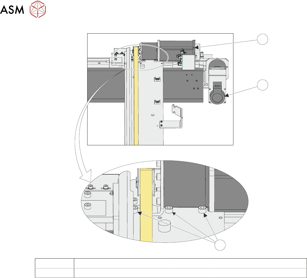
15
16
17
15 Camera X Motor 17 Securing Screws
16 Camera Y Motor
► Using a soft headed mallet gently tap the edge of the camera X axis support platform to close
the gap on the camera alignment pins.
NOTE
The camera can be severely damaged if excessive force is used to position the camera axis.
► Tighten the three securing screws taking care not to allow the position to slip.
► Check for parallelism again.
► Parallelism Complete - Remove the location jig from the rising table.
► Fit the board clamp to the front rail.
► Refit the stencil.
► Close the printhead cover.
► Press the System button.
► Select Exit.
► Select Exit.
► Select Back.
17.3.4 Y Axis Parallelism
The Y axis parallelism is factory set and is not adjustable.
17 CAMERA SYSTEM MODULE
17.3 ADJUSTMENTS AND SETTINGS
TECHNICAL REFERENCE MANUAL Vol 1 E By DEK 04/2019 271
17.3.5 Vision Height for Standard Rail System
WARNING
BOARD CLAMPS. EXTREME CARE MUST BE EXERCISED WHEN WORKING IN
THE TOOLING AREA OF THE MACHINE TO AVOID INJURY. THE FOILS ON THE
FRONT AND REAR BOARD CLAMPS ARE VERY SHARP.
NOTE
Ensure the board file used has the correct board thickness value. Check rail / camera X motor
bracket clearance. Remember that the vision height may be higher if a thinner board is used.
► If required, select Unload Screen.
► Open the printhead cover.
► Remove the stencil from the machine.
► Place the board on the rails and slide to a central position.
► Refit the stencil.
► Close the printhead cover.
► Press the System button.
► Select Load Screen.
► Select Maintenance.
► Select Diagnostics.
► Using the Next or Previous button highlight Rising Table.
► Select Select Module.
► Using the Next or Previous button highlight Raise Table To Vision Height.
► Select Run Diagnost.
► Remove the left hand safety cover.
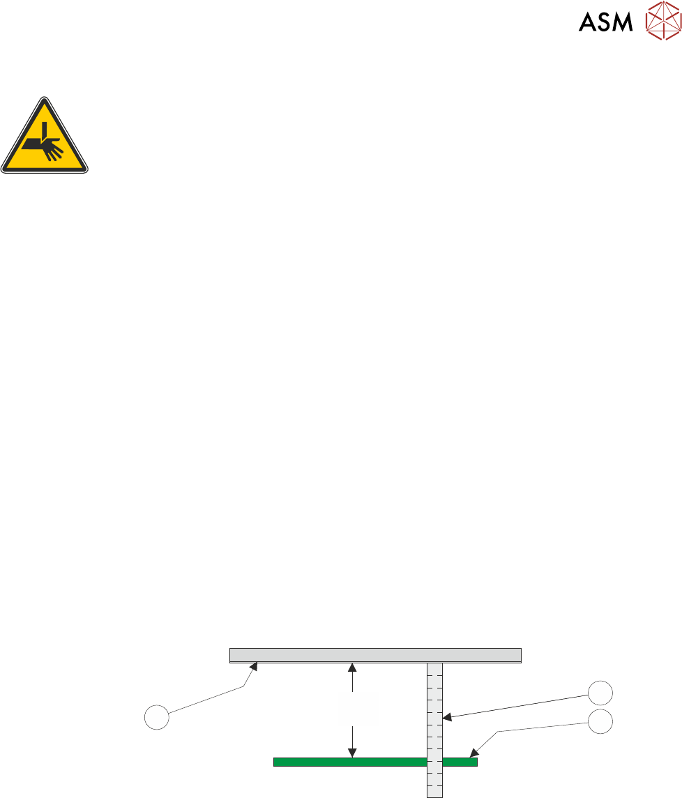
► Using a suitable metric rule, measure the distance between the bottom of the stencil to the top
of the board. Check that the dimension is 78mm -0.0mm / +0.2mm, (ie the height cannot be
less than 78.0mm).
78.0mm
(-0.0mm / +0.2mm)
11
3
2
1
► If the dimension is correct, go to Adjustment Complete.
► Using the Next or Previous button highlight Drive Table Using Jog Buttons.
► Select Run Diagnost.
► Using jog buttons drive the rising table to achieve a vision height of 78mm -0.0mm / +0.2mm,
(ie the height cannot be less than 78.0mm).
NOTE
1. The rising table must not be jogged up higher than the specified dimension, camera damage
may occur.
2. The right jog button drives the rising table up, the left jog button drives the rising table down.
► Using the Next or Previous button highlight Set Reference Vision Height.
17 CAMERA SYSTEM MODULE
17.3 ADJUSTMENTS AND SETTINGS
272 TECHNICAL REFERENCE MANUAL Vol 1 E By DEK 04/2019
► Select Run Diagnost. The message ‘This Will Alter The Printer ConfigurationFile - Please
Confirm’ is displayed.
► Select Confirm.
► Using the Next or Previous button highlight Home Rising Table.
► Select Run Diagnost.
► Adjustment Complete - Refit the left hand safety cover.
► Select Exit.
► Select Exit.
► Remove the board from the rails.
► Select Back.
► If the vision height has been adjusted a vision calibration and an offset calibration must be
carried out.
17.3.6 Camera Focus
The camera focus is factory set and sealed and should not need adjustment.
17.3.7 Camera Reference Position
► Select Maintenance.
► Select Diagnostics.
► Using the Next or Previous button highlight Camera Axes.
► Select Select Module.
► Using the Next or Previous button highlight Home Camera X Axis.
► Select Run Diagnost.
► Using the Next or Previous button highlight Home Camera Y Axis.
► Select Run Diagnost.
► Using the Next or Previous button highlight Initialise Vision System.
► Select Run Diagnost.
► Select Drive to Reference Position.
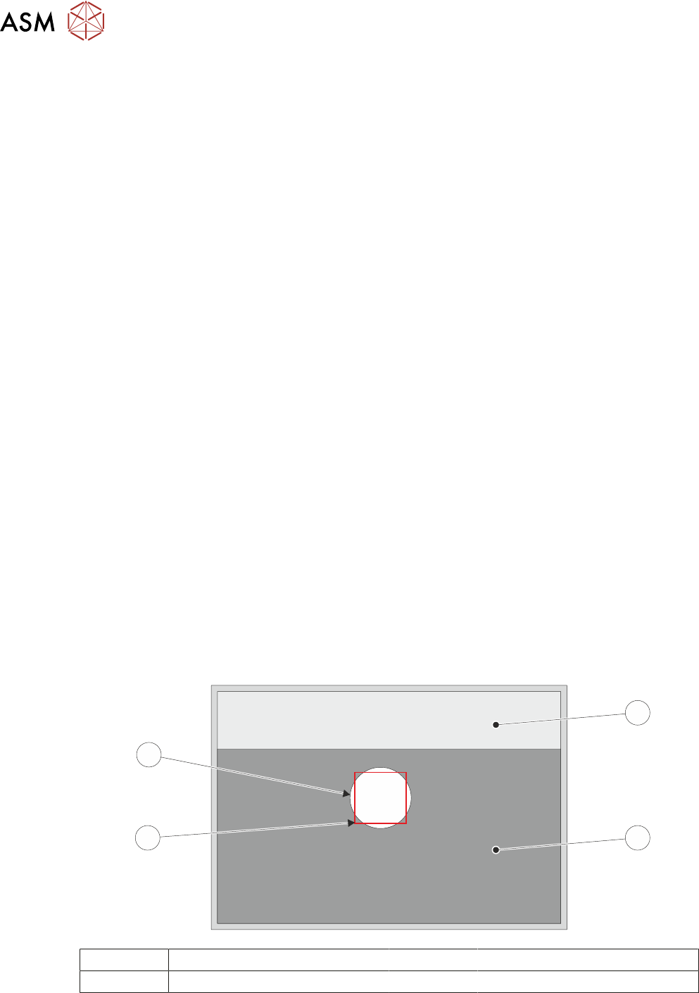
► Select Run Diagnost, a box and the white dot on the board clamp are visible on the monitor.
1
2
3
4
1 Board Clamp Foil 3 Box
2 Board Clamp 4 White Dot
► If the reference position is correct, go to Reference Correct.
► Using Move Camera X Axis Using Jog Buttons and Move Camera Y Axis Using Jog But-
tons, position the box centrally inside the white dot, as shown in the illustration.