03217917-01-01E By DEK Technical Reference Manual Vol 1_enPDFA.pdf - 第186页
14 SCREEN ALIGNMENT MODULE 14.1 OVERVIEW 186 TECHNICAL REFERENCE MANUAL Vol 1 E By DEK 04/2019 The stencil is aligned to the board on each machine cycle unless non-vision is selected. An al- gorithm determined by image c…
14 SCREEN ALIGNMENT MODULE
14.1 OVERVIEW
TECHNICAL REFERENCE MANUAL Vol 1 E By DEK 04/2019 185
14
SCREEN ALIGNMENT MODULE
14.1 OVERVIEW
1
2
2
1
9
8
7
6
5
2
4
3
2
A
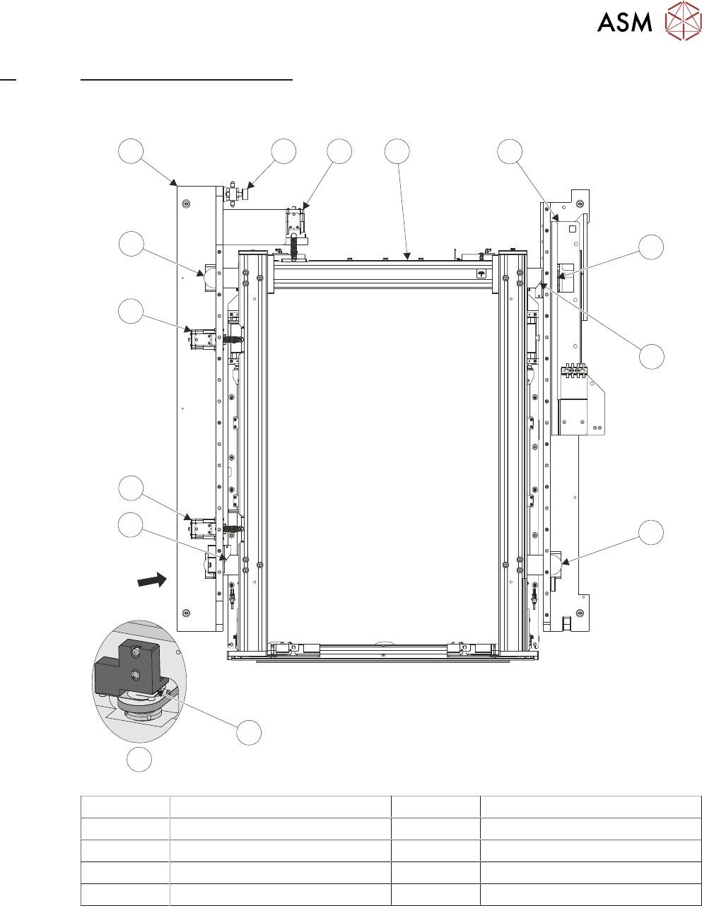
A View on Arrow 5 Left Hand Printhead Assembly
1 Chase Clamp (2 positions) 6 Chase Clamp Regulator
2 Roller Counter Plate (4 positions) 7 Y Actuator
3 X Front Actuator 8 AWSM
4 X Rear Actuator 9 Right Hand Printhead Assembly
The screen alignment system is one of the most sensitive and critical components of machine ac-
curacy. The alignment system consists of three stepper motor driven linear actuators in contact
with the chase (adjustable screen mount) which is a free floating mechanism sprung against the
three actuators. The actuators are configured in a three point contact arrangement and are con-
trolled and driven independently to give maximum flexibility in stencil movement.

14 SCREEN ALIGNMENT MODULE
14.1 OVERVIEW
186 TECHNICAL REFERENCE MANUAL Vol 1 E By DEK 04/2019
The stencil is aligned to the board on each machine cycle unless non-vision is selected. An al-
gorithm determined by image capture is calculated in software, this sets the direction and distance
that each actuator must move to align the stencil to the board. Once correctly aligned the chase is
clamped by two pneumatic chase clamps, to the left and right printhead assemblies, so that the
alignment is maintained throughout the rest of the print cycle.
A spring fitted between the actuator and the chase provides an anti-backlash mechanism to ensure
accurate positioning is always achieved.
All positioning of the screen actuators is referenced from the home position and calculated in the
machine software. The screen actuators only home during initialisation, which can be from power-
up or exiting diagnostics. When homed the stepper motor retracts the actuator plunger until the mo-
tor stalls. The stepper motor reverses direction and drives the actuator plunger out 20mm.
For information on the chase clamp solenoid and the chase clamp regulator refer to the Pneumat-
ics Chapter in Volume 2 of this manual.
14 SCREEN ALIGNMENT MODULE
14.2 ELECTRICAL SCHEMATIC
TECHNICAL REFERENCE MANUAL Vol 1 E By DEK 04/2019 187
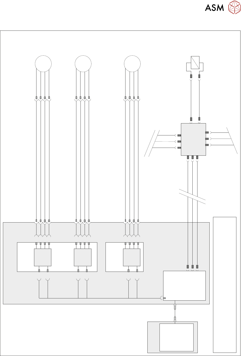
14.2 ELECTRICAL SCHEMATIC
Dual Stepper
X1
Y
Actuator
9M07
8PL05
8SK05
M
3
5
7
1
M36PL25
1
3
5
7
Dual Stepper
X3
Step 2
SK3
a2
a4
a6
a8
c26
SK3
c28
Dir 2
Step 2
X Rear
Actuator
9M06
8PL04
8SK04
M
3
5
7
1
M36PL24
1
3
5
7
SK1
c2
c4
c6
c8
Step 1
a30
SK1
c30
Dir 1
Step 1
X Forward
Actuator
9M05
8PL03
8SK03
M
3
5
7
1
M36PL23
1
3
5
7
Step 0
SK1
a2
a4
a6
a8
c26
SK1
c28
Dir 0
Step 0
M36 Machine
Control Enclosure
PC
Motherboard
NextMove ES
(I/O Node 1)
1
2
4
CAN_H
CAN_L
CAN GND
M36PL35
SK5
CAN Bus
CAN
Out
NODE
Power
N2SK3
N2SK1
Main Machine
I/O Node 2
N2SK2
CAN In
16SK31
Chase
Clamps
16SOL31
DIG OUT 7
N2PL4
0V
7
2
3
7
2
3
1
14
NOTE
The breaks in the CAN Bus chain reflect that additional I/O Nodes
may be fitted, refer to Machine Control chapter for the complete
CAN Bus chain.
USB