03217917-01-01E By DEK Technical Reference Manual Vol 1_enPDFA.pdf - 第36页
3 SAFETY FEATURES 3.5 LOCKOUT 36 TECHNICAL REFERENCE MANUAL Vol 1 E By DEK 04/2019 3.5.2 Pneumatic Lockout W ARNING COMPRESSED AIR. COMPRESSED AIR SHOULD NEVER IMPINGE UPON THE BODY . PORTS, PIPES, ETC MUST NEVER BE BLOC…
3 SAFETY FEATURES
3.5 LOCKOUT
TECHNICAL REFERENCE MANUAL Vol 1 E By DEK 04/2019 35
3.5 LOCKOUT
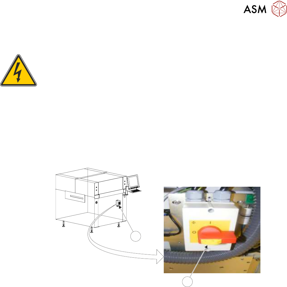
3.5.1 Electrical Lockout
WARNING
LETHAL VOLTAGE. DANGEROUS VOLTAGES EXIST IN THIS EQUIPMENT.
ENSURE ALL ELECTRONIC COVERS AND MAIN MACHINE COVERS ARE FITTED
BEFORE OPERATING THIS EQUIPMENT.
Electrical lockout of the printer is achieved by applying a padlock, or any other suitable locking
device, through the body and the switch shroud of the mains isolator switch. This can only be
achieved when the mains isolator switch is in the OFF position.
To electrically lockout the printer, carry out the following procedure:
► Close down the printer software.
► Switch the mains isolator (2) to the OFF position.
► Pull the lockout tab out (1).
► Fit a padlock or suitable locking device through the lockout point.
1
2
NOTE
Switch shown in the OFF position.
► This completes the electrical lockout.

3 SAFETY FEATURES
3.5 LOCKOUT
36 TECHNICAL REFERENCE MANUAL Vol 1 E By DEK 04/2019
3.5.2 Pneumatic Lockout
WARNING
COMPRESSED AIR. COMPRESSED AIR SHOULD NEVER IMPINGE UPON THE
BODY. PORTS, PIPES, ETC MUST NEVER BE BLOCKED BY HAND. BEFORE
CONNECTING OR DISCONNECTING ANY PNEUMATIC COMPONENTS, ENSURE
THE COMPRESSED AIR SUPPLY HAS BEEN DISSIPATED AND DISCONNECTED
FROM THE MACHINE.
Pneumatic lockout of the printer is achieved by:
► Close down the printer software.
► Switch the electrical mains isolator to the OFF position.
► Turn OFF the factory’s main pneumatic supply to the printer.
► Dissipate remaining air in the pneumatic supply line.
► Disconnect the pneumatic supply line from the printer.
► This completes the pneumatic lockout.
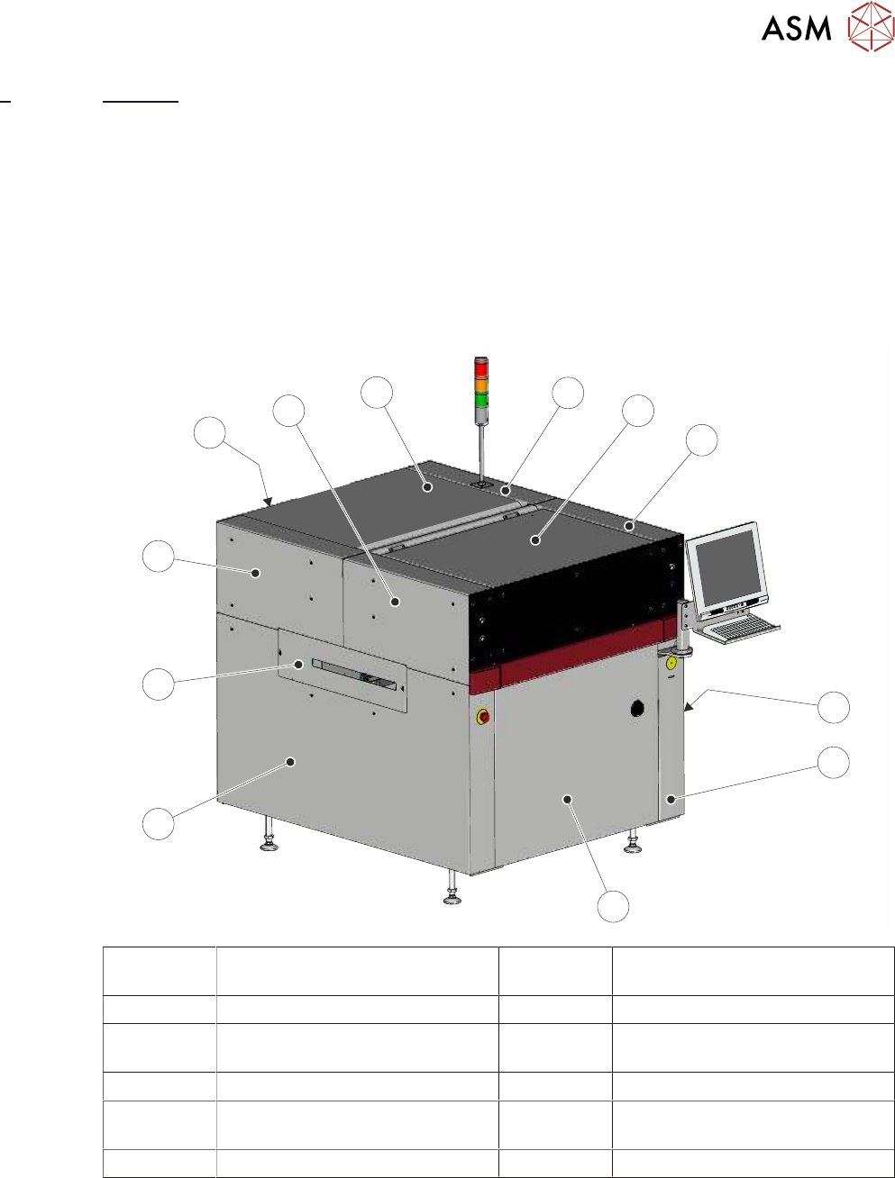
4 COVERS
4.1 PRINTER COVERS
TECHNICAL REFERENCE MANUAL Vol 1 E By DEK 04/2019 37
4
COVERS
4.1 PRINTER COVERS
In order to protect personnel and prevent damage to the printer, four panels are fitted around the
base of the printer.
●
Front Panel
●
Rear Panel
●
Lower Side Panels (2 positions)
The upper part of the printer is protected by the front printhead cover, two front corner panels, two
rear corner panels and an upper rear panel.
1
2
3
4
5
6
7
8
9
10
11
12
1 Right Hand Upper Rear Corner
Panel
7 Left Hand Side Cover
2 Front Printhead Cover 8 Left Hand Safety Cover
3 Right Hand Upper Front Corner
Panel
9 Left Hand Upper Rear Corner
Panel
4 Right Hand Safety Cover 10 Lower Rear Panel
5 Right Hand Side Cover 11 Left Hand Upper Front Corner
Panel
6 Front Panel 12 Upper Rear Panel
NOTE
Some of the covers can only be removed in a specific order due to the covers interlocking with
each other.