03217917-01-01E By DEK Technical Reference Manual Vol 1_enPDFA.pdf - 第62页
6 POWER SUPPLY M37 6.1 OVERVIEW 62 TECHNICAL REFERENCE MANUAL Vol 1 E By DEK 04/2019 The PSU is a Switched Mode Power Supply Unit (SMPSU) which converts the ac into the following dc supplies: ● +24V US ● +24V SW ● +5.5V …
6 POWER SUPPLY M37
6.1 OVERVIEW
TECHNICAL REFERENCE MANUAL Vol 1 E By DEK 04/2019 61
6
POWER SUPPLY M37
6.1 OVERVIEW
3
6
5
4
3
2
1
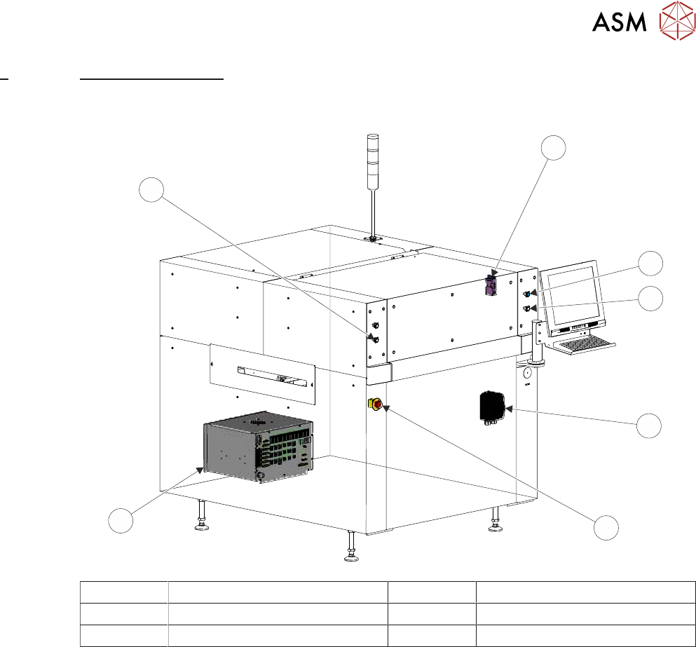
1 Front Printhead Cover Interlock 4 Mains Isolator Switch
2 System Button 5 E Stop Button
3 Two Button Control 6 M37 Power Supply Enclosure
Mains input power (100V to 240V) to the machine is routed to the mains isolator switch at the front
of the machine. From the mains isolator it is fed to the M37 power supply crate, through the cable
gland at the rear panel, to the three terminal blocks TB1 (live), TB2 (neutral) and TB3 (earth). From
the terminal blocks mains power is supplied to the following:
●
M37SK31 PC Supply
●
M37SK32 Monitor Supply
●
M37SK33 Spare
●
M37SK34 Spare
●
M37SK35 Internal Vac Pump via Mains Filter and CB34
●
PSU

6 POWER SUPPLY M37
6.1 OVERVIEW
62 TECHNICAL REFERENCE MANUAL Vol 1 E By DEK 04/2019
The PSU is a Switched Mode Power Supply Unit (SMPSU) which converts the ac into the following
dc supplies:
●
+24V US
●
+24V SW
●
+5.5V
●
+12V
●
-12V
●
+42V
The dc supplies from the PSU are fed to the power distribution PCB. The optional PSU monitor
board, which enables monitoring of the power supplies, is mounted on the power distribution PCB.
An E Stop loop, front cover interlock, rear cover interlock/interlock blanking plug and E Stop relay
are fitted to ensure motor power is removed if the printhead cover or rear cover is opened or the
machine is crash stopped by pressing an E Stop button.
A two handed safety relay, left jog button and right jog button are fitted to enable certain functions
to be performed with the printhead cover open.
The M37 power supply crate has mains power available; when access to the components of the
enclosure is required, observe the following warning:
WARNING
LETHAL VOLTAGE. DANGEROUS VOLTAGES EXIST IN THIS EQUIPMENT.
ENSURE ALL ELECTRONIC COVERS AND MAIN MACHINE COVERS ARE FITTED
BEFORE OPERATING THIS EQUIPMENT.
6 POWER SUPPLY M37
6.2 ELECTRICAL SCHEMATIC
TECHNICAL REFERENCE MANUAL Vol 1 E By DEK 04/2019 63
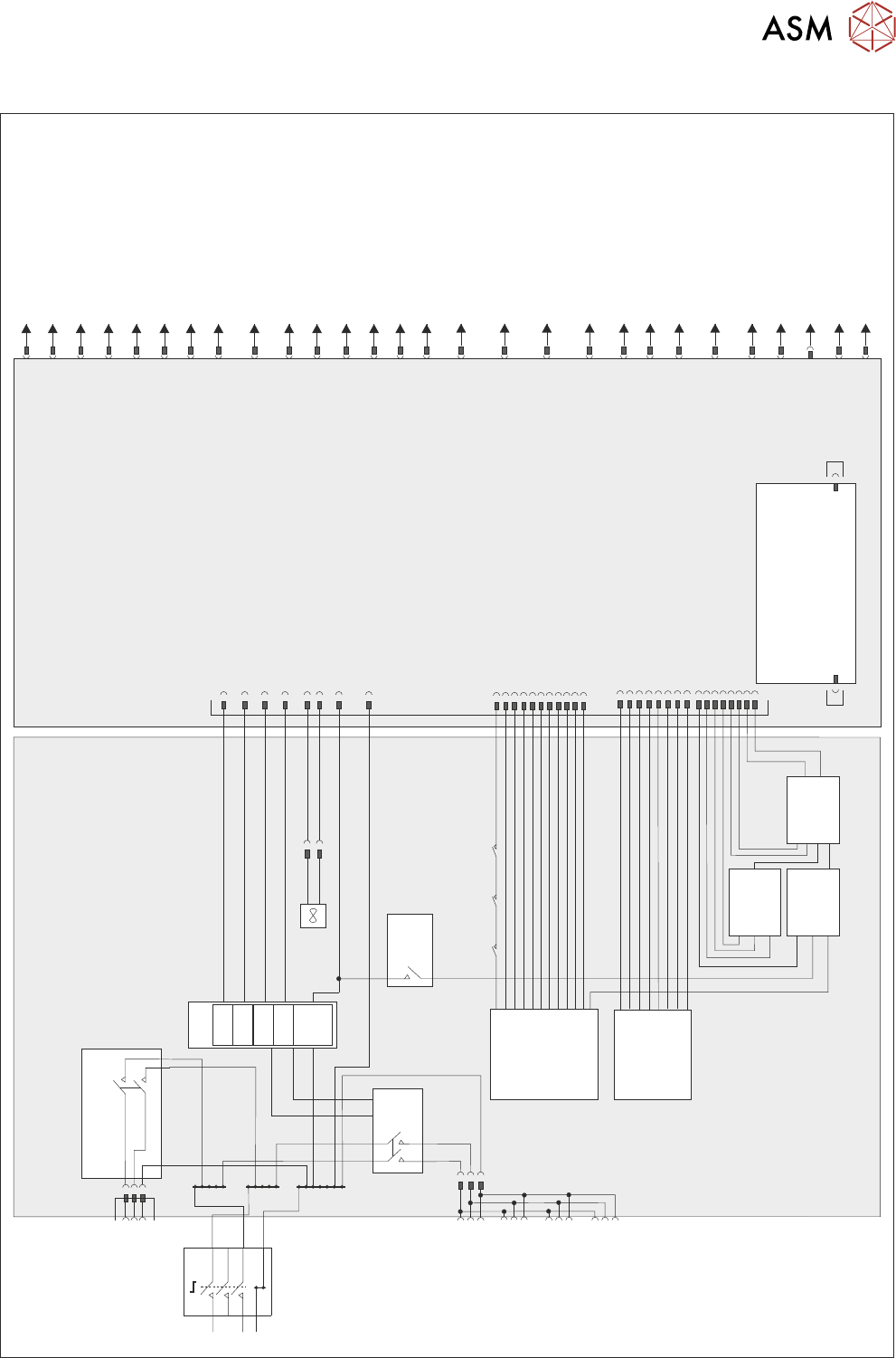
6.2 ELECTRICAL SCHEMATIC
M37 Power Supply Crate
CB 32
10A
PSU
+24V
-12V
+12V
+5.5V
Internal Vac Pump
CB34
16A
TB2
TB3
L
N
E
Mains Isolator
TB1
M37SK31
PC Supply
M37SK32
Monitor Supply
M37SK33
Spare
M37SK34
Spare
M37SK35
Internal Vac Supply
CB33
10A
2 Handed
Safety Relay
PIHZ X1
RL2
E Stop Relay
PNOZ X2
RL1
M37TB01
Power Distribution PCB
M37SK36
Part
CON1
Part
CON2
Part
CON3
CON 1
CON 3
CON 2
Fan
PSU Monitor Board
M37PL28
M37PL29
MMI
M37SK27
Safety I/O
M37PL26
M37SK24
E Stop Blanking Plug
M37SK30
USB Port
M37SK23
Rear Cover Interlock -
Interlock Blanking Plug
M37SK22
Front Cover Interlock
M37SK21
Spare Servo Motor Power
M37SK20
Not Used
M37SK19
Camera Y I/O Node 9
Servo Motor Power
M37SK18
Camera X I/O Node 8
Servo Motor Power
Spare
M37SK01
Rising Table I/O Node 6
Servo Motor Power
M37SK16
M37SK17
Print Carriage I/O Node 7
Servo Motor Power
Low Current DC
M37SK02
High Current DC
M37SK03
Machine I/O Node 2
M37SK04
Print Carriage I/O Node 3
M37SK05
USC I/O Node 4
M37SK06
Not Used
M37SK07
Not Used
M37SK08
Not Used
M37SK09
Grid-Lok
M37SK10
Internal Lighting
M37SK11
+12V Spare
M37SK12
Remote Barcode Reader
M37SK13
Hand Held Barcode Reader
M37SK14
Machine Fans
M37SK15
M37SK25
E Stop Buttons
+42V
/+48V