03217917-01-01E By DEK Technical Reference Manual Vol 1_enPDFA.pdf - 第27页
3 SAFETY FEATURES 3.2 GENERAL TECHNICAL REFERENCE MANUAL Vol 1 E By DEK 04/2019 27 3.2 GENERAL DEK printing machines incorporate safety features that provide a safe operating environment for the operator and the machine.…
3 SAFETY FEATURES
3.1 OVERVIEW
26 TECHNICAL REFERENCE MANUAL Vol 1 E By DEK 04/2019
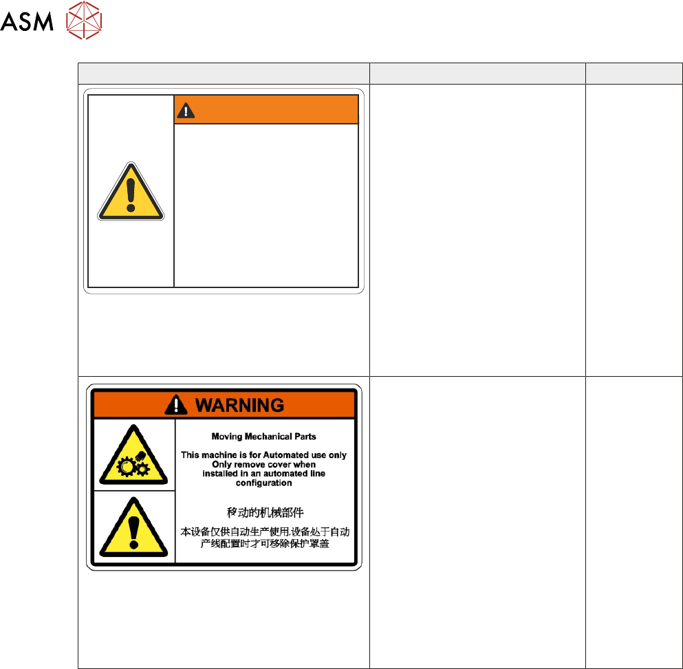
Warning Definition Location
WARNING / DANGER
Electro Mechanical Hazards
Removing cover could result
in serious injury
Disconnect and lock out system
power before servicing refer to
the Technical Reference manual
Dangers électromécaniques
Retirer les capots ou couvercles peut
entraîner des blessures graves.
Déconnecter et couper l alimentation
électrique avant deffectuer lentretien
de la machine, se référer
au Manuel de Référence Technique.
ELECTRO MECHANICAL HAZ-
ARDS
REMOVING THIS COVER EX-
POSES ELECTRO MECHAN-
ICAL PARTS THAT HAVE THE
POTENTIAL TO CAUSE SERI-
OUS INJURY. DISCONNECT
AND LOCK OUT THE SYSTEM
POWER BEFORE REMOVING
THIS COVER. REFER TO THE
LOCKOUT PROCEDURE AT
THE END OF THIS CHAPTER.
GENERAL WARNING
REFER TO THE OPERATOR
MANUAL OR THE FRONT OF
THIS CHAPTER FOR A LIST OF
ALL WARNINGS AND DEFINI-
TIONS.
REAR
COVER
ELECTRO MECHANICAL HAZ-
ARDS
REMOVING THIS COVER EX-
POSES ELECTRO MECHAN-
ICAL PARTS THAT HAVE THE
POTENTIAL TO CAUSE SERI-
OUS INJURY. DISCONNECT
AND LOCK OUT THE SYSTEM
POWER BEFORE REMOVING
THIS COVER. REFER TO THE
LOCKOUT PROCEDURE AT
THE END OF THIS CHAPTER.
GENERAL WARNING
REFER TO THE OPERATOR
MANUAL OR THE FRONT OF
THIS CHAPTER FOR A LIST OF
ALL WARNINGS AND DEFINI-
TIONS.
SAFETY
COVERS
3 SAFETY FEATURES
3.2 GENERAL
TECHNICAL REFERENCE MANUAL Vol 1 E By DEK 04/2019 27
3.2 GENERAL
DEK printing machines incorporate safety features that provide a safe operating environment for
the operator and the machine.
All safety circuits have been designed to meet the safety requirements as outlined in the machines’
CE Declaration of Conformity. The circuits check for welded contacts before resetting. Additional
safety is achieved by duplication of the power contactors to provide redundancy.
1
2
3
4
5
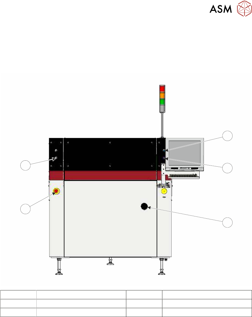
1 System Button 4 E Stop Button
2 Right Jog Button 5 Left Jog Button
3 Mains Isolator Switch
3 SAFETY FEATURES
3.2 GENERAL
28 TECHNICAL REFERENCE MANUAL Vol 1 E By DEK 04/2019
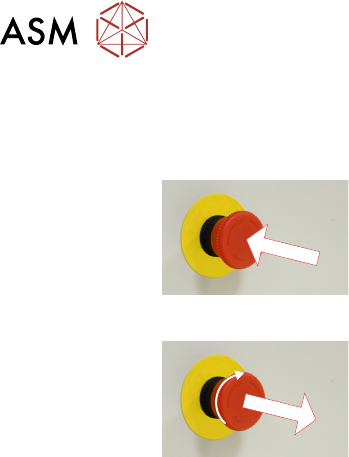
3.2.1 Emergency Stop (E Stop)
The machine is fitted with an E Stop which suspends all machine operations. The switch is within
easy reach of the operator and once pressed, the latching switch requires resetting.
To reset the E Stop, turn the button clockwise until it unlatches.
Pressing the E Stop or opening the printhead cover cuts the servo axes power supply. A warning of
this condition is reported on the machine monitor.
3.2.1.1 E Stop Module Shut Down
If the E Stop loop is opened by pressing the E Stop or opening the printhead cover, an emergency
stop is initiated via the E Stop module. When actuated the following areas of the machine are
rendered inactive:
●
Lid Bolt
●
Moving Rail Stepper
●
Print Carriage Servo (axis stopped before power is removed)
●
Rail System Front and Rear Belt Motor Drives
●
Rising Table Brake (brake engages when power is cut)
●
Rising Table Servo
●
Squeegee Stepper Motor(s)
●
System Lamp
●
Understencil Cleaner Paper Feed Motor
●
Understencil Cleaner Solvent Pump
●
Understencil Cleaner Squeegee Solenoid
●
Vacuum Tooling Solenoid
●
X Camera Motor (axis stopped before power is removed)
●
X Forward, X Rear and Y Chase Alignment Stepper Motors
●
Y Camera Motor (axis stopped before power is removed)
3.2.1.2 Recovery
When normal working conditions are restored, release the E Stop switch and, when prompted by a
screen message, press the System button.