03217917-01-01E By DEK Technical Reference Manual Vol 1_enPDFA.pdf - 第159页
11 SQUEEGEE MODULE 11.3 REPLACEMENT PROCEDURES TECHNICAL REFERENCE MANUAL Vol 1 E By DEK 04/2019 159 ► Remove the printhead mechanism by unscrewing the four screws (4) securing the unit to the print carriage. ► Placing t…
11 SQUEEGEE MODULE
11.3 REPLACEMENT PROCEDURES
158 TECHNICAL REFERENCE MANUAL Vol 1 E By DEK 04/2019
11.3.1.2 Front Squeegee Drive Belt (Green Label)
To replace the front squeegee drive belt (left hand stepper motor), the printhead mechanism must
be removed from the print carriage.
► Select Open Cover Commands.
► Select Carriage To Front.
► Select Back.
► Select Shut Down.
► Select Continue.
► Switch the mains isolator to OFF; lockout the isolator switch.
► Open the printhead cover.
► Remove the squeegees, if fitted.
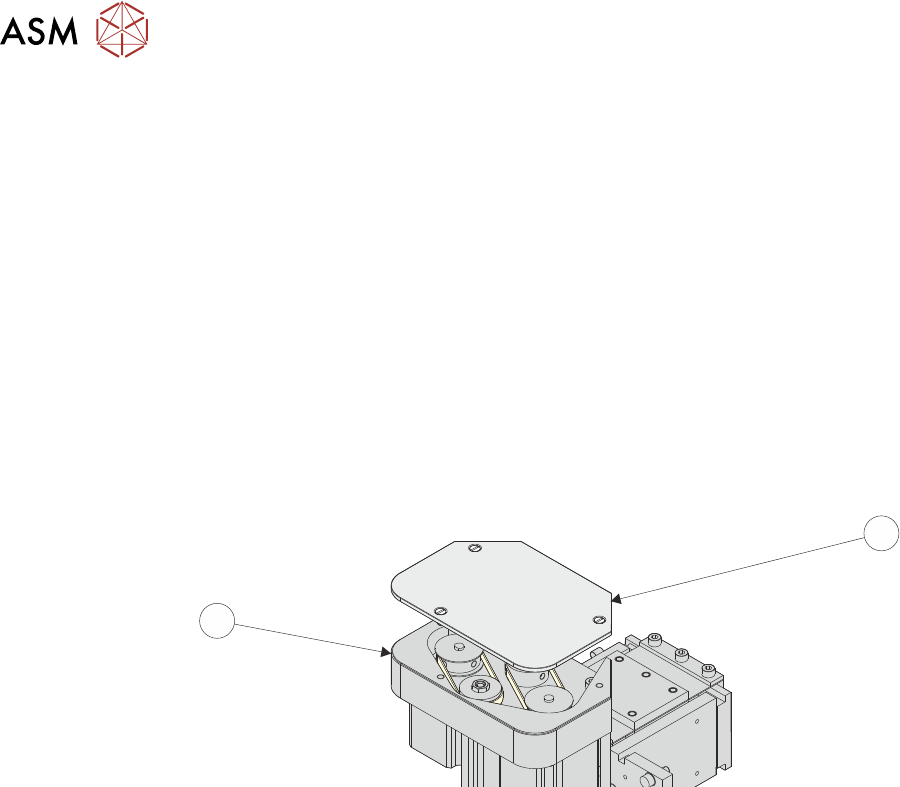
► Remove the drive belt cover plate (1) from the squeegee printhead mechanism (2) and
remove the broken drive belt.
1
2
► Disconnect the following connectors from the print carriage, left hand side.
●
Rear Squeegee Motor
●
Front Squeegee Motor
●
Home Sensors
●
Squeegee Pressure Amplifier
11 SQUEEGEE MODULE
11.3 REPLACEMENT PROCEDURES
TECHNICAL REFERENCE MANUAL Vol 1 E By DEK 04/2019 159
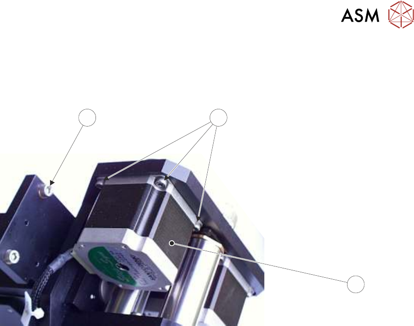
► Remove the printhead mechanism by unscrewing the four screws (4) securing the unit to the
print carriage.
► Placing the unit on a secure surface, slacken off the three screws (5) securing the left hand
motor (3) to the support plate.
4
5
3
Squeegee Stepper Motor (Green Ident Label Shown)
► Fit the new belt in position.
► Using a cable tie wrap or similar, provide a loop around the top of the body of the motor en-
abling the motor to be pulled using a force meter. Ensure that the force meter is pulled in the
direction which the drive belt is fitted, 11.3.1.1 "Rear Squeegee Drive Belt (Green La-
bel)" [}156] figure example refers.
► Pull the force meter until a tension of 3-4kgs is monitored on the meter. Tighten the three
screws (5) whilst the motor is under tension.
► On completion re-fit the printhead mechanism to the print carriage refit the drive belt cover
plate and re-connect all leads to the print carriage, left hand side.
► Refit the squeegees.
► Close the printhead cover.
► Remove the isolator lock; turn the mains isolator ON.
► Press the System button.
11 SQUEEGEE MODULE
11.3 REPLACEMENT PROCEDURES
160 TECHNICAL REFERENCE MANUAL Vol 1 E By DEK 04/2019
11.3.1.3 Alternative Drive Belt Replacement (Non-Green Label)
This replacement procedure applies to both front and rear belts. It is advised that drive belts are re-
placed as a pair.
NOTE
The pulley hole centres are fixed. There is no need for pulley belt tension adjustment.
The squeegee drive belts can be replaced without having to remove the printhead mechanism from
the print carriage.
► Select Open Cover Commands.
► Select Carriage To Front.
► Select Back.
► Select Shut Down.
► Select Continue.
► Switch the mains isolator to OFF; lockout the isolator switch.
► Open the printhead cover.
► Remove the squeegees, if fitted.
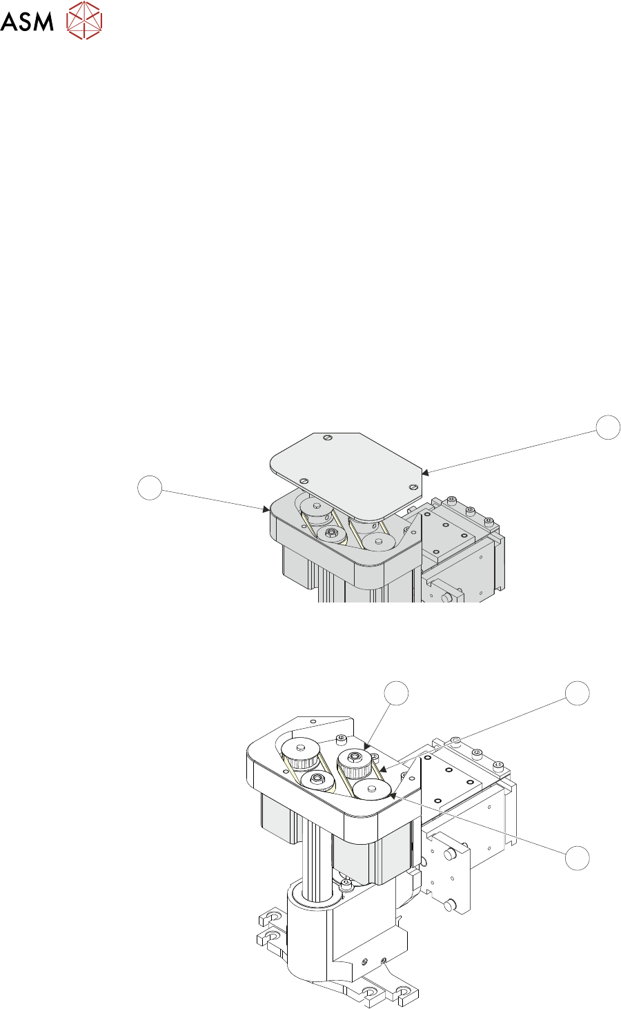
► Remove the drive belt cover plate (1) from the squeegee printhead mechanism (2).
1
2
► Pull the drive belt (3) from its centre and slip it up over the idler pulley (5).
► Slip the belt (3) over the drive pulley (4) and discard it.
3
5
4