03217917-01-01E By DEK Technical Reference Manual Vol 1_enPDFA.pdf - 第56页
5 MACHINE OVERVIEW 5.1 MODULE OVERVIEWS 56 TECHNICAL REFERENCE MANUAL Vol 1 E By DEK 04/2019 5.1.14 Print Carriage Module The print carriage module is the vehicle that transports the following: ● Squeegee Module ● Stenci…
5 MACHINE OVERVIEW
5.1 MODULE OVERVIEWS
TECHNICAL REFERENCE MANUAL Vol 1 E By DEK 04/2019 55
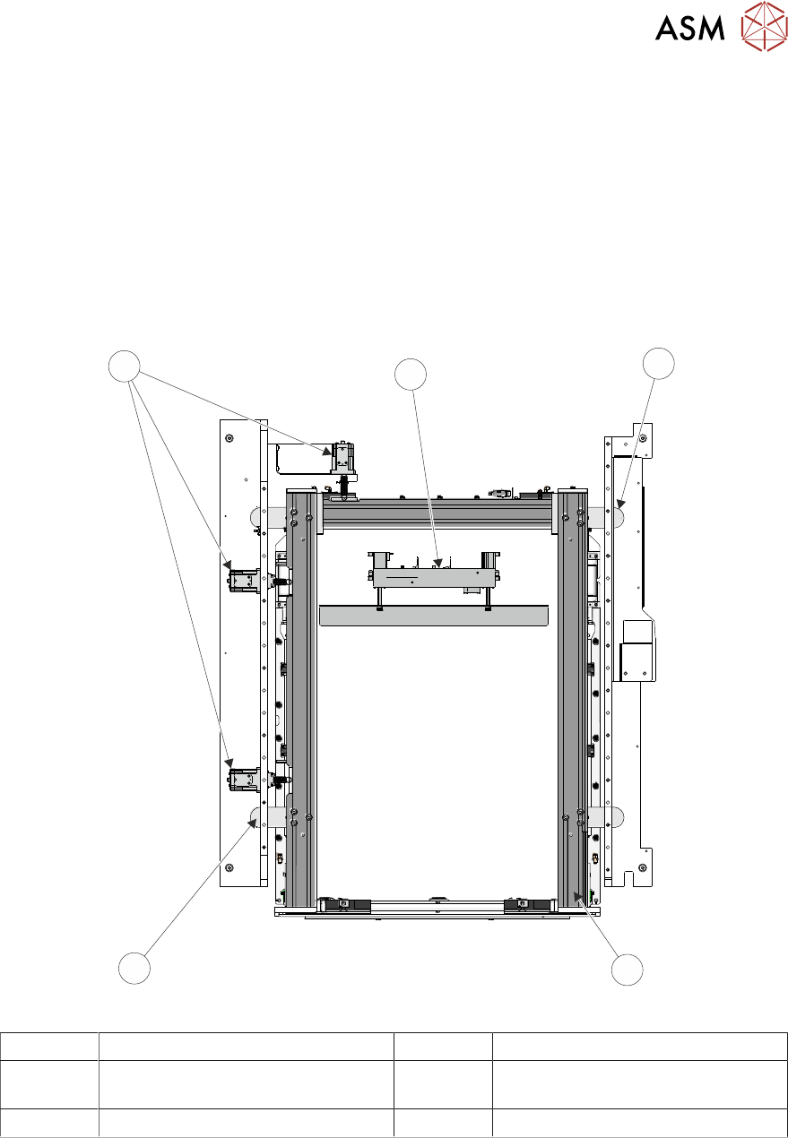
5.1.12 Adjustable Width Screen Mount (AWSM)
The AWSM is the receptacle for the stencil during printing operations. The AWSM is fully ad-
justable to accommodate the most popular of stencil sizes. The print stencil is clamped into place
by the AWSM during the print cycle. The AWSM is a machine option replacing the C Chase.
The stencil change mechanism locates the stencil within the chase assembly.
5.1.13 Screen Alignment Module
The screen alignment module enables adjustment of the AWSM to achieve optimum stencil to
board alignment prior to the print stroke. Actuators move the print stencil in the X, Y and theta
planes to nullify the misalignment error signal from the vision system.
5
4
3
2
1
1 Chase Clamp (Stencil Alignment) 4 Actuators (Stencil Alignment)
2 Adjustable Width Stencil Mount
(AWSM)
5 Stencil Change Mechanism
3 Chase Clamp (Stencil Alignment)
5 MACHINE OVERVIEW
5.1 MODULE OVERVIEWS
56 TECHNICAL REFERENCE MANUAL Vol 1 E By DEK 04/2019
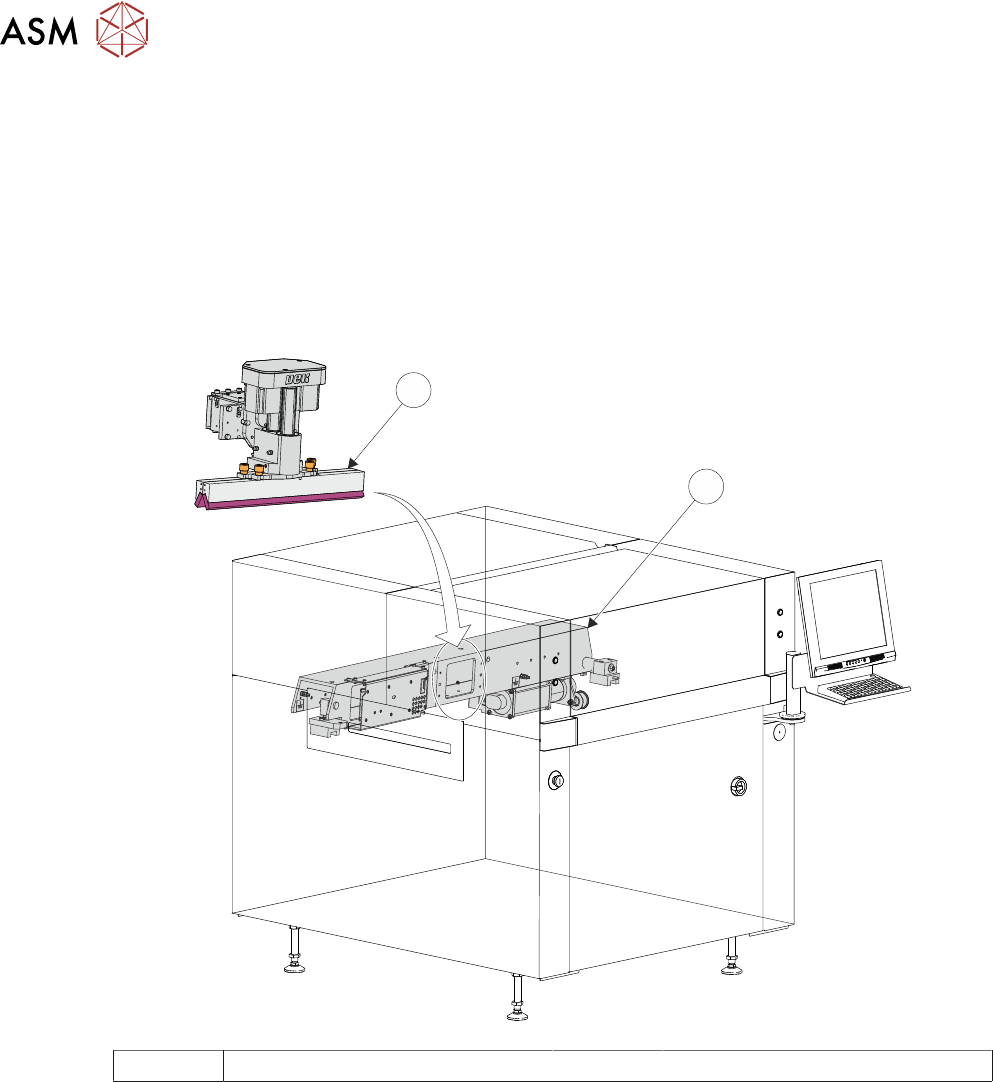
5.1.14 Print Carriage Module
The print carriage module is the vehicle that transports the following:
●
Squeegee Module
●
Stencil Change Module
5.1.15 Squeegee Module
The function of the squeegee module is to apply the print material through the stencil image onto
the board in a controlled manner. Squeegee height and downward pressure is monitored during the
print stroke to optimize the print quality.
2
1
1 Print Carriage 2 Squeegee Module
5 MACHINE OVERVIEW
5.1 MODULE OVERVIEWS
TECHNICAL REFERENCE MANUAL Vol 1 E By DEK 04/2019 57
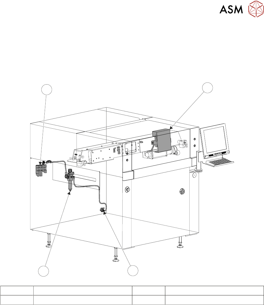
5.1.16 Pneumatics Module
The function of the pneumatics module is to supply regulated air pressure to the pneumatic devices
throughout the machine. The air supply is routed to the required pneumatic device via an electric-
ally operated solenoid valve controlled by the machine control system.
There are two banks of pneumatic solenoids, one located on the rear frame of the machine and the
other located on the print carriage.
1
2
4
3
1 Print Carriage Solenoid Bank 3 Regulator/Filter
2 Pneumatics Input 4 Rear Solenoid Bank