03217917-01-01E By DEK Technical Reference Manual Vol 1_enPDFA.pdf - 第187页
14 SCREEN ALIGNMENT MODULE 14.2 ELECTRICAL SCHEMATIC TECHNICAL REFERENCE MANUAL Vol 1 E By DEK 04/2019 187 14.2 ELECTRICAL SCHEMATIC Dual Stepper X1 Y Actuator 9M07 8P L 05 8S K 05 M 3 5 7 1 M36P L 25 1 3 5 7 Dual Steppe…

14 SCREEN ALIGNMENT MODULE
14.1 OVERVIEW
186 TECHNICAL REFERENCE MANUAL Vol 1 E By DEK 04/2019
The stencil is aligned to the board on each machine cycle unless non-vision is selected. An al-
gorithm determined by image capture is calculated in software, this sets the direction and distance
that each actuator must move to align the stencil to the board. Once correctly aligned the chase is
clamped by two pneumatic chase clamps, to the left and right printhead assemblies, so that the
alignment is maintained throughout the rest of the print cycle.
A spring fitted between the actuator and the chase provides an anti-backlash mechanism to ensure
accurate positioning is always achieved.
All positioning of the screen actuators is referenced from the home position and calculated in the
machine software. The screen actuators only home during initialisation, which can be from power-
up or exiting diagnostics. When homed the stepper motor retracts the actuator plunger until the mo-
tor stalls. The stepper motor reverses direction and drives the actuator plunger out 20mm.
For information on the chase clamp solenoid and the chase clamp regulator refer to the Pneumat-
ics Chapter in Volume 2 of this manual.
14 SCREEN ALIGNMENT MODULE
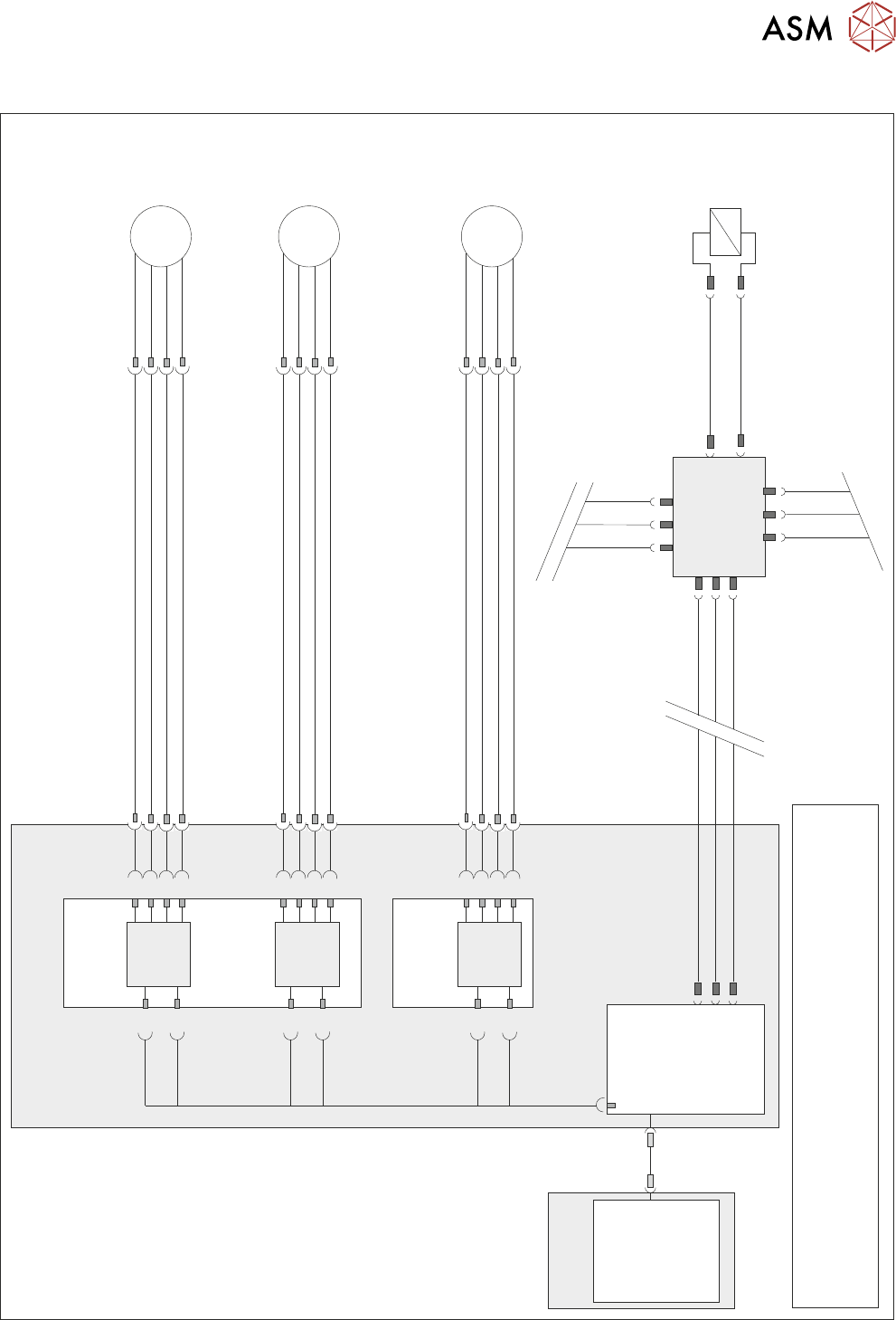
14.2 ELECTRICAL SCHEMATIC
TECHNICAL REFERENCE MANUAL Vol 1 E By DEK 04/2019 187
14.2 ELECTRICAL SCHEMATIC
Dual Stepper
X1
Y
Actuator
9M07
8PL05
8SK05
M
3
5
7
1
M36PL25
1
3
5
7
Dual Stepper
X3
Step 2
SK3
a2
a4
a6
a8
c26
SK3
c28
Dir 2
Step 2
X Rear
Actuator
9M06
8PL04
8SK04
M
3
5
7
1
M36PL24
1
3
5
7
SK1
c2
c4
c6
c8
Step 1
a30
SK1
c30
Dir 1
Step 1
X Forward
Actuator
9M05
8PL03
8SK03
M
3
5
7
1
M36PL23
1
3
5
7
Step 0
SK1
a2
a4
a6
a8
c26
SK1
c28
Dir 0
Step 0
M36 Machine
Control Enclosure
PC
Motherboard
NextMove ES
(I/O Node 1)
1
2
4
CAN_H
CAN_L
CAN GND
M36PL35
SK5
CAN Bus
CAN
Out
NODE
Power
N2SK3
N2SK1
Main Machine
I/O Node 2
N2SK2
CAN In
16SK31
Chase
Clamps
16SOL31
DIG OUT 7
N2PL4
0V
7
2
3
7
2
3
1
14
NOTE
The breaks in the CAN Bus chain reflect that additional I/O Nodes
may be fitted, refer to Machine Control chapter for the complete
CAN Bus chain.
USB

14 SCREEN ALIGNMENT MODULE
14.3 TEST CYCLES
188 TECHNICAL REFERENCE MANUAL Vol 1 E By DEK 04/2019
14.3 TEST CYCLES
Carry out the following procedure to access the Test Cycles:
► Select Maintenance.
► Select Test Cycles.
► The following options are displayed:
●
Dry Align Test
●
Accuracy Test
●
Data Logging On/Off
14.3.1 Dry Align Test
Selecting this function initiates the machine to run Dry Alignment accuracy tests.
With data logging set to On, all test data is output to a Test.log file. With data logging set to Off, all
test data is output to a Test.dat file.
14.3.2 Accuracy Test
Selecting this function commences a series of 4 tests:
●
Operation of the vision camera
●
Movement of the camera
●
Repeatabiltiy of the rising table and rail system
●
Operation of the chase clamps.
With data logging set to On, all test data is output to an atest.dat file that can be imported into a Lo-
tus spreadsheet to assist in determining the cause of location accuracy problems associated with
camera positioning, chase clamping and table movement. Pressing the Stop Run key at any time
during the sequence of tests terminates the cycle on completion of the respective test and return to
the previous menu.
To recommence the test cycle select Accuracy Test, this starts the tests at Test 1 again and not
where the test cycle was previously terminated.
14.3.3 Data Logging On/Off
Selecting this function enables/disables data logging from within the main menu without the neces-
sity of entering the diagnostics mode.
With data logging enabled, the following data files are created on the PC hard drive giving informa-
tion on certain machine functions:
●
Camera.dat
●
Fiducial.dat
●
Inspect.dat
●
Pressure.dat
●
Ptest.dat
●
Screen.dat
14.3.3.1 Camera.dat
This file is created when cycle camera system is running in diagnostics and records fiducial loca-
tions for each camera cycle.
14.3.3.2 Fiducial.dat
This file is created at the end of the calibration function and records fiducial detection data for the
50 locations.
14.3.3.3 Inspect.dat
This file is created by SPC and records 2Di paste results in a raw data format.