03217917-01-01E By DEK Technical Reference Manual Vol 1_enPDFA.pdf - 第37页
4 COVERS 4.1 PRINTER COVERS TECHNICAL REFERENCE MANUAL Vol 1 E By DEK 04/2019 37 4 COVERS 4.1 PRINTER COVERS In order to protect personnel and prevent damage to the printer, four panels are fitted around the base of the …

3 SAFETY FEATURES
3.5 LOCKOUT
36 TECHNICAL REFERENCE MANUAL Vol 1 E By DEK 04/2019
3.5.2 Pneumatic Lockout
WARNING
COMPRESSED AIR. COMPRESSED AIR SHOULD NEVER IMPINGE UPON THE
BODY. PORTS, PIPES, ETC MUST NEVER BE BLOCKED BY HAND. BEFORE
CONNECTING OR DISCONNECTING ANY PNEUMATIC COMPONENTS, ENSURE
THE COMPRESSED AIR SUPPLY HAS BEEN DISSIPATED AND DISCONNECTED
FROM THE MACHINE.
Pneumatic lockout of the printer is achieved by:
► Close down the printer software.
► Switch the electrical mains isolator to the OFF position.
► Turn OFF the factory’s main pneumatic supply to the printer.
► Dissipate remaining air in the pneumatic supply line.
► Disconnect the pneumatic supply line from the printer.
► This completes the pneumatic lockout.
4 COVERS
4.1 PRINTER COVERS
TECHNICAL REFERENCE MANUAL Vol 1 E By DEK 04/2019 37
4
COVERS
4.1 PRINTER COVERS
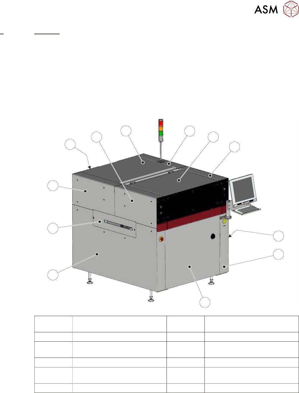
In order to protect personnel and prevent damage to the printer, four panels are fitted around the
base of the printer.
●
Front Panel
●
Rear Panel
●
Lower Side Panels (2 positions)
The upper part of the printer is protected by the front printhead cover, two front corner panels, two
rear corner panels and an upper rear panel.
1
2
3
4
5
6
7
8
9
10
11
12
1 Right Hand Upper Rear Corner
Panel
7 Left Hand Side Cover
2 Front Printhead Cover 8 Left Hand Safety Cover
3 Right Hand Upper Front Corner
Panel
9 Left Hand Upper Rear Corner
Panel
4 Right Hand Safety Cover 10 Lower Rear Panel
5 Right Hand Side Cover 11 Left Hand Upper Front Corner
Panel
6 Front Panel 12 Upper Rear Panel
NOTE
Some of the covers can only be removed in a specific order due to the covers interlocking with
each other.
4 COVERS
4.1 PRINTER COVERS
38 TECHNICAL REFERENCE MANUAL Vol 1 E By DEK 04/2019
4.1.1 Cover Removal
Before removing any covers ensure that the supplies (air and electrical) have been isolated from
the printer.
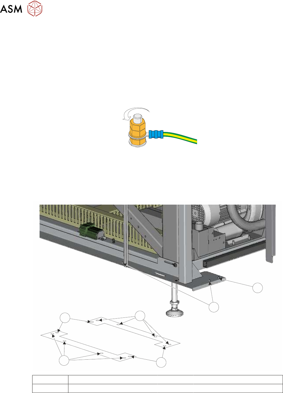
4.1.1.1 Earth Bonding
All external metal surfaces are mechanically and electrically bonded to the printer earth point. The
bonding wire used is identified by its green and yellow insulation and is commonly used to earth
bond throughout.
Using an 8mm spanner, remove the two earth lead securing nuts and washer. Detach the earth
lead from the panel.
Care should be taken when removing these links, to ensure that when they are replaced they are
secured tightly and cleanly.
4.1.1.2 Locating Pins
Side, corner, front and rear panels are secured on location pins at the base of the printer. Plates
mounted on each corner of the printer (see vignette below) house the pins.
1
2
1
2
3
2
1 Front Panel Location Pins 3 Rear Panel Location Pins
2 Side Panel Location Pins