03217917-01-01E By DEK Technical Reference Manual Vol 1_enPDFA.pdf - 第31页
3 SAFETY FEATURES 3.4 HIGH VOLTAGE PROTECTION TECHNICAL REFERENCE MANUAL Vol 1 E By DEK 04/2019 31 3.4 HIGH VOLTAGE PROTECTION 3.4.1 Access Where incoming supply voltages are present, protection is afforded by controllin…

3 SAFETY FEATURES
3.3 PRINTHEAD COVER
30 TECHNICAL REFERENCE MANUAL Vol 1 E By DEK 04/2019
3.3 PRINTHEAD COVER
3.3.1 Safety Interlocks
The safely features designed into the printer are for the protection of all operators and maintenance
personnel. ASM strongly recommended safety devices are never overridden.
Opening the printhead cover allows access to the following areas:
●
Printhead
●
Squeegee
●
Stencil
●
Under Stencil Cleaner
●
Tooling
The printhead cover is accessible to the operator and an interlock safety switch protects personnel
from the mechanisms during normal line operations. Lifting the cover cuts power to all motors and
selected actuators, via the E Stop module, to all printer modules,
Pneumatically operated lid bolt(s) prevent the cover being raised during the print cycle. The lid bolt
is withdrawn and the cover may be raised:
●
When Open Cover is requested by software
●
When pause or stop is selected during a print cycle
●
When the E Stop is pressed
3.3.2 Recovery
When the printhead cover is closed, normal working condition is restored and the line may be re-
started. Pressing the system button enables resumption of operations, where this is allowed by the
control system.
3 SAFETY FEATURES
3.4 HIGH VOLTAGE PROTECTION
TECHNICAL REFERENCE MANUAL Vol 1 E By DEK 04/2019 31
3.4 HIGH VOLTAGE PROTECTION
3.4.1 Access
Where incoming supply voltages are present, protection is afforded by controlling access to the en-
closures that house the supply. The printer is fitted with a mains isolator switch that cuts power to
all circuits located beyond the switch.
3.4.2 Hazard Warning Labels
Hazard warning labels are placed on the outside of enclosures where dangerous voltage
(100V-240V) terminations are present within.
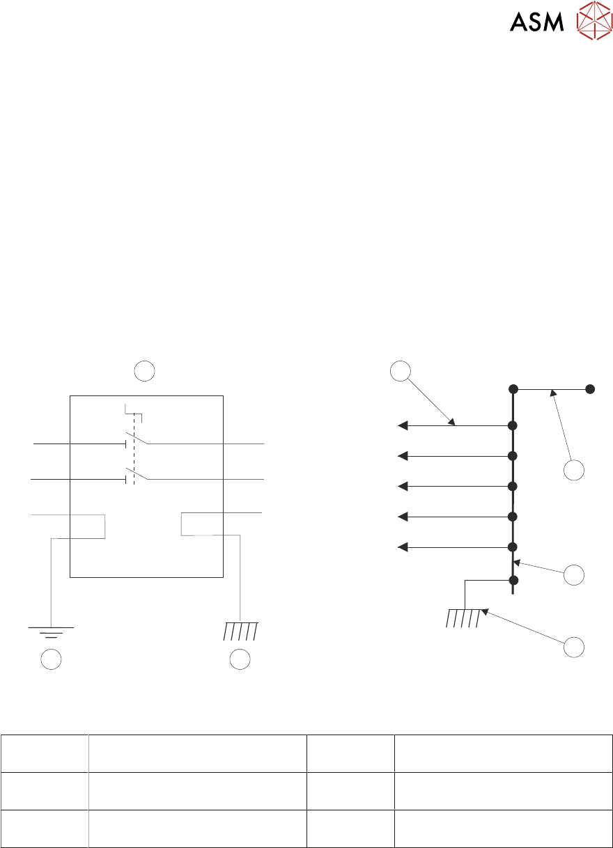
3.4.3 Earth Bonding
All external metal surfaces are mechanically and electrically bonded to the printer’s protected earth
point. The bonding wire used is identified by its green and yellow insulation and is commonly used
to earth bond throughout. Care should be taken when removing these links that when they are re-
placed they are secured tightly and cleanly.
L
L
L1
T1
L2
T2
N
N
E
E
1
2
6
3
3
4
5
Printer Protected Earth Point
1 PSU M37 Module Earth Bond
Stud
4 Printer Protective Earth Chassis
Stud
2 Earth Busbar 5 Earth Busbar Connected to
Printer Frame
3 Printer Bonding Earth Chassis
Stud
6 Printer Earth Connections
3 SAFETY FEATURES
3.4 HIGH VOLTAGE PROTECTION
32 TECHNICAL REFERENCE MANUAL Vol 1 E By DEK 04/2019
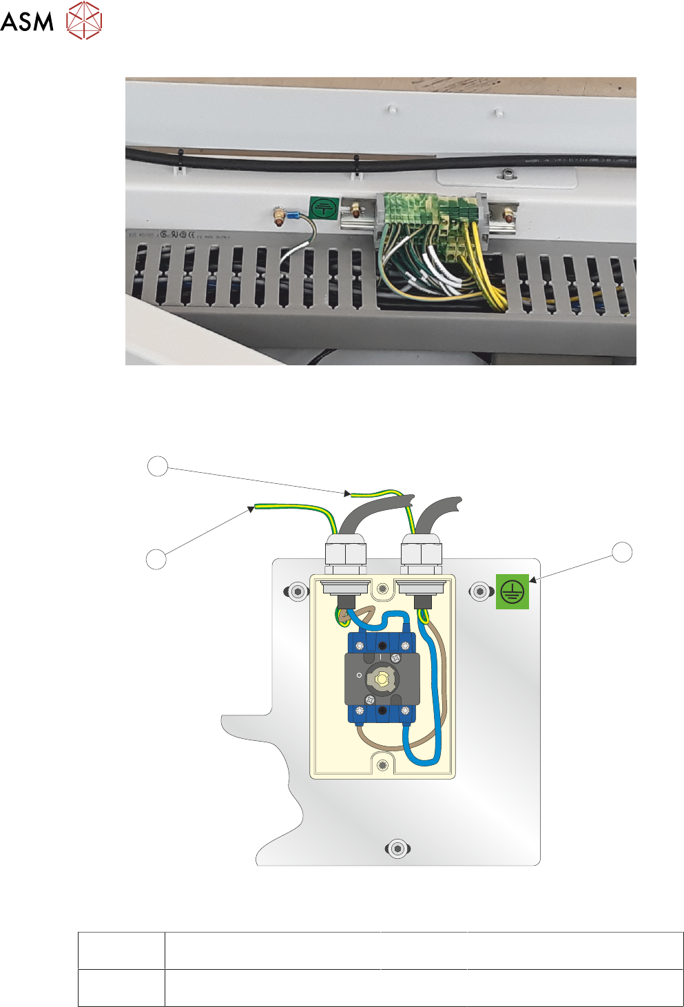
Printer Protected Earth Stud and Earth Busbar - Earth Point and Labels (RHS of Printer
Chassis)
OFF
ON
L1 L2
T1 T2
1
3
2
Mains Isolator (Cover Removed) Showing Earth Loom Arrangement
1 Earth Label 3 Earth Lead to Chassis M5 Stud
and TB3
2 Earth Lead to Chassis M6 Stud
(Protective Earth)