03217917-01-01E By DEK Technical Reference Manual Vol 1_enPDFA.pdf - 第233页
16 TRANSPORT RAILS MODULE 16.4 ADJUSTMENTS AND SETTINGS TECHNICAL REFERENCE MANUAL Vol 1 E By DEK 04/2019 233 16.4 ADJUSTMENTS AND SETTINGS 16.4.1 Rail Lifted Sensors ► Select Maintenance . ► Select Diagnostics . ► Selec…
16 TRANSPORT RAILS MODULE
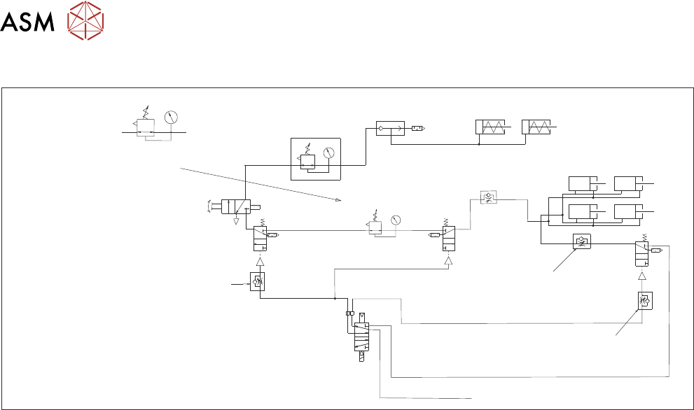
16.3 PNEUMATIC SCHEMATIC
232 TECHNICAL REFERENCE MANUAL Vol 1 E By DEK 04/2019
16.3 PNEUMATIC SCHEMATIC
5/2
16SOL10
A B
Clamp
Speed
Control
Unclamp Delay Control
Fitted at Solenoid
Valve on Rear of M/C
Board Clamps
Snuggers
Out
In
Pressure Control
Snuggers On
Board Clamp
Reg (optional)
Snugger Delay
(Control)
In
Out
Mains Input
Out To Board
Clamps
16 SOL10 (A) In
E By DEK Board Clamp Regulator
NOTE
Only one regulator fitted;
dependent on option in use.
16 TRANSPORT RAILS MODULE
16.4 ADJUSTMENTS AND SETTINGS
TECHNICAL REFERENCE MANUAL Vol 1 E By DEK 04/2019 233
16.4 ADJUSTMENTS AND SETTINGS
16.4.1 Rail Lifted Sensors
► Select Maintenance.
► Select Diagnostics.
► Select Confirm.
► From the displayed table, select Rising Table.
► Select Home Table.
► Select Back.
► From the displayed table, select Rail System from the table.
► Select Home Rails.
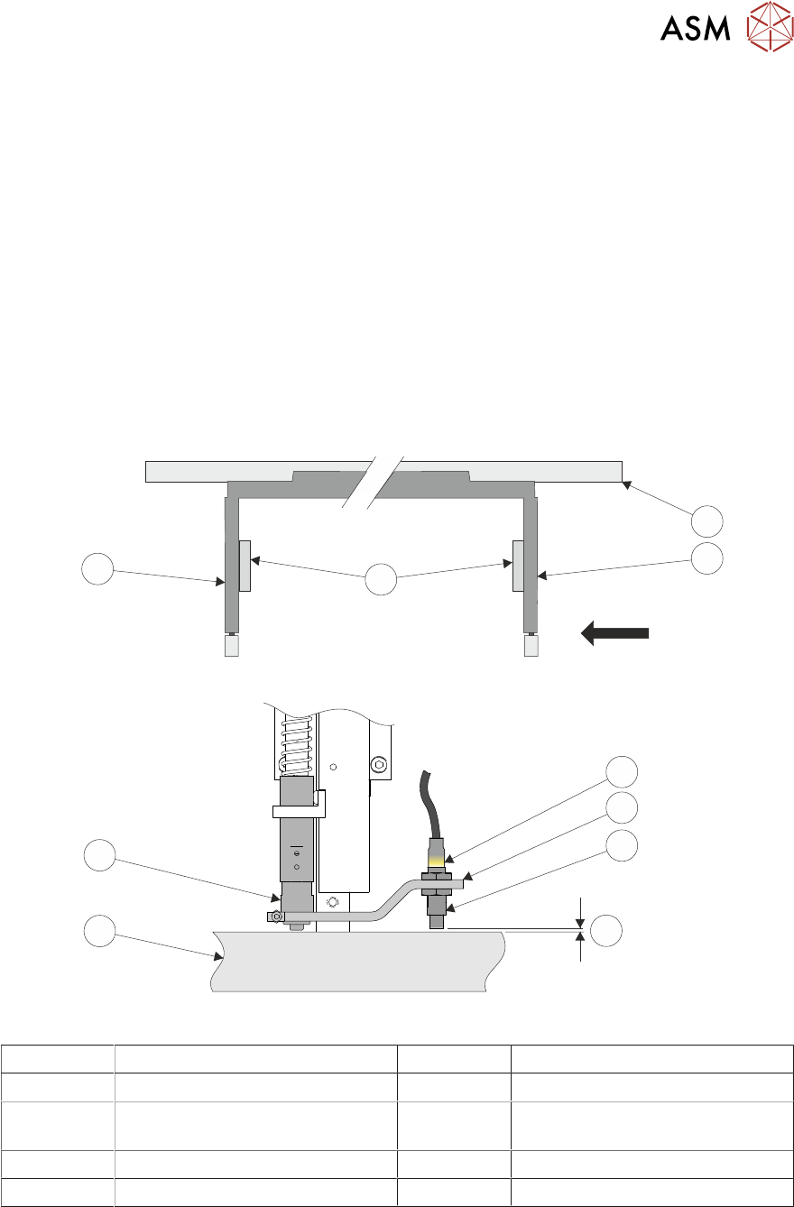
► Remove the left and right hand side safety covers to gain access to the rear rail.
► Identify the rear right rail transport leg and the rail stop bar (clatter bar).
View on Arrow
4
3
1
2
5
6
7
8
9
10
1 Rear Rail 6 Sensor Support Bracket
2 Right Transport Leg 7 Sensor
3 Linear Bearings 8 3.5mm GO
4mm NO GO
4 Left Transport Leg 9 Rail Stop Bar (Clatter Bar)
5 Sensor LED 10 Shock Absorber
► Adjust the sensor position, so that a 3.5mm gauge fits between the sensor and the top face of
the clatter bar and a 4mm gauge does not fit.
► Repeat previous Step for left hand end of the rear rail.
► Select Board Width parameter.
► Enter a value of 40.5mm (minimum board width), and select Accept.

16 TRANSPORT RAILS MODULE
16.4 ADJUSTMENTS AND SETTINGS
234 TECHNICAL REFERENCE MANUAL Vol 1 E By DEK 04/2019
► Select Rails To Board Width.
► Adjust the sensor position, so that a 3.5mm gauge fits between the sensor and the top face of
the clatter bar and a 4mm gauge does not fit, at the rear right rail transport leg. Repeat for left
hand end of the rail.
► Select Back.
► Select Exit Diagnostics.
► Select Confirm.