03217917-01-01E By DEK Technical Reference Manual Vol 1_enPDFA.pdf - 第263页
17 CAMERA SYSTEM MODULE 17.1 OVERVIEW TECHNICAL REFERENCE MANUAL Vol 1 E By DEK 04/2019 263 17 CAMERA SYSTEM MODULE 17.1 OVERVIEW 1 2 3 4 5 6 7 8 9 10 1 1 12 13 14 15 1 Camera Y Home Sensor 9 Camera Assembly 2 Camera Y H…
16 TRANSPORT RAILS MODULE
16.6 CALIBRATIONS
262 TECHNICAL REFERENCE MANUAL Vol 1 E By DEK 04/2019
3
► Select Next.
► Select Incr. or Decr. to start the belts running left to right.
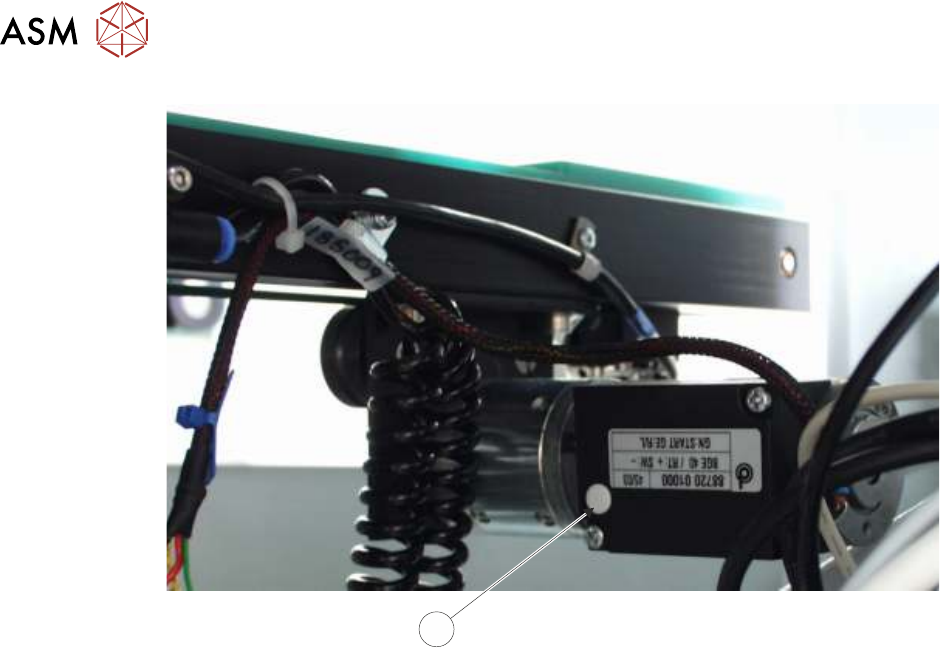
► Ensure that one of the following speeds is achieved for both the front and rear belts:
●
29 to 31 metres/min for standard transport rails.
●
37 to 39 metres/min for heavy board transport rails.
NOTE
There is no separate adjustment between left to right and right to left. If the above speed is not
achievable in both directions, the motor may be faulty.
► Select Exit.
► Select Exit.
► Select Back.
► Refit the safety cover.
17 CAMERA SYSTEM MODULE
17.1 OVERVIEW
TECHNICAL REFERENCE MANUAL Vol 1 E By DEK 04/2019 263
17
CAMERA SYSTEM MODULE
17.1 OVERVIEW
1
2
3
4
5
6
7
8
9
10
11
12
13
14
15
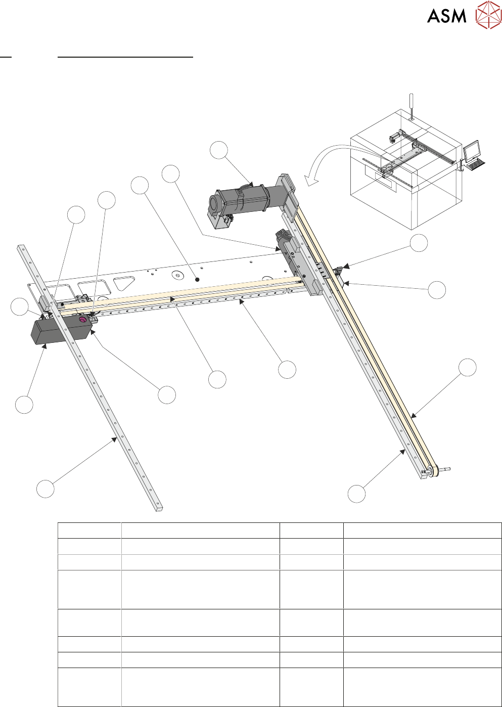
1 Camera Y Home Sensor 9 Camera Assembly
2 Camera Y Home Vane 10 Camera X Home Vane
3 Y Axis Drive Belt 11 Camera X Home Sensor
4 Y Axis Right Hand Linear Bearing
(mounted on bottom of right hand
printhead)
12 Camera Mounted Board Stop and
Board Stop Extended Sensor
5 X Axis Linear Bearing 13 Camera X Axis Support Platform
(shown transparent for clarity)
6 X Axis Timing Belt 14 Camera X Motor Node 8
7 Board at Stop Sensor 15 Camera Y Motor Node 9
8 Y Axis Left Hand Linear Bearing
(mounted on bottom of Left hand
printhead)

17 CAMERA SYSTEM MODULE
17.1 OVERVIEW
264 TECHNICAL REFERENCE MANUAL Vol 1 E By DEK 04/2019
The camera assembly traverses horizontally in the X and Y axis to position the camera to carry out
the following functions:
●
Board Stop
●
Fiducial Capture - for stencil to board alignment
●
Site Capture - pre and post printing for 2Di inspection
●
Moving the Underscreen Cleaner
Positioning of the camera assembly is carried out by the X and Y drive mechanisms.
The camera contains an optical unit for image focusing and a lighting unit for board and stencil illu-
mination during fiducial and 2D camera capture operations.
The camera carriage also contains the following:
●
Camera Board Stop
●
Board at Stop sensor
●
Board Stop Extended Sensor
The camera board stop is a pneumatically driven unit which is lowered to stop the board in position
ready for clamping and vision alignment to take place.
The board at stop diffuse background suppressed opto detects the board when it reaches the
board stop. This starts a timer which when elapsed stops the belts and clamps the board.
The board stop extended sensor is fitted to ensure that the board stop is raised before any camera
carriage movement is demanded.
The camera positions are referenced from the home position. Each camera axis only homes during
initialisation, which can be from power-up or exiting diagnostics.
The camera system also provides the drive mechanism for the under screen cleaner.
The camera used by the camera system is the Hawkeye 750.