03217917-01-01E By DEK Technical Reference Manual Vol 1_enPDFA.pdf - 第221页
15 BOARD STOP 15.6 ADJUSTMENTS AND SETTINGS TECHNICAL REFERENCE MANUAL Vol 1 E By DEK 04/2019 221 ► Loosen the base clamp securing screw (4) sufficiently, using a 4mm Allen key, to remove the base clamp (1) from the mach…
15 BOARD STOP
15.6 ADJUSTMENTS AND SETTINGS
220 TECHNICAL REFERENCE MANUAL Vol 1 E By DEK 04/2019
► Select Back.
► Select Back.
15.6.7.2 External Services
► Select Shut Down.
► Select Continue.
► Switch the mains isolator to OFF.
► Disconnect the quick release mains air connection at the rear the machine.
► Remove the machine rear cover.
► At the board stop solenoid (16SOL14), on the pneumatic manifold at the rear of the machine:
► Remove the pipe marked Remote/B/Stop Up - RH from the front port (A).
► Remove the pipe marked Remote/B/Stop Down - RH from the in-line flow controller, self-seal
connector fitted to the rear port (B).
► Fit the pipe marked Remote/B/Stop Up - LH to the front port (A).
► Fit the pipe marked Remote/B/Stop Down - LH to the in-line flow controller, self-seal con-
nector fitted to the rear port (B).
► Fit the rear cover.
15.6.7.3 Fitting the Remote Board Stop
► Open the front printhead cover.
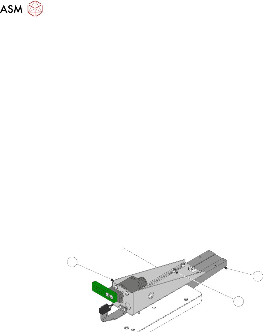
► At the remote board stop assembly:
●
Disconnect 8PL05 from 8SK05R.
●
Disconnect the pipe from the in-line connector on the pipe marked 1.
●
Disconnect the pipe from the in-line connector on the pipe marked 2.
► Remove the four M5 cap head screws and washers (2) from the board stop assembly (3) us-
ing a 5mm Allen key.
1
2
3
► Remove the board stop assembly (3) from the machine.
15 BOARD STOP
15.6 ADJUSTMENTS AND SETTINGS
TECHNICAL REFERENCE MANUAL Vol 1 E By DEK 04/2019 221
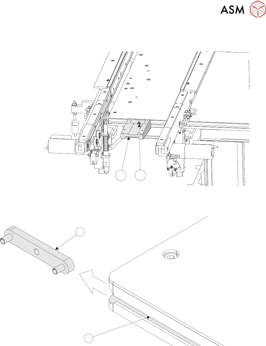
► Loosen the base clamp securing screw (4) sufficiently, using a 4mm Allen key, to remove the
base clamp (1) from the machine.
1
4
► Remove the base clamp locating nut (5) from the attachment slot (6) on the right hand side of
the rising table.
6
5
15 BOARD STOP
15.6 ADJUSTMENTS AND SETTINGS
222 TECHNICAL REFERENCE MANUAL Vol 1 E By DEK 04/2019
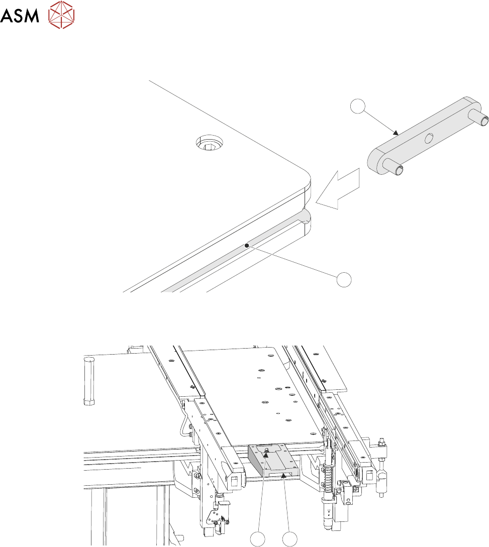
► Fit the base clamp locating nut (5) into the attachment slot (6) on the left hand side of the
rising table.
6
5
► Attach the base clamp (1) to the locating nut (5), in the correct position in the Y axis for the
product, using a 4mm Allen key and M5 securing screw and washer (4).
4
1
► Mark the centre point, in the X axis, on the front of the product board.
► Place the product board on the rails with the board centre point at the Camera Reference Po-
sition (white dot on front rail).
► Before fitting the remote board stop assembly (3) to the base clamp (1), ensure that the board
stop is configured for left hand side operation, carry out 15.6.2.1 "LHS Configuration" [}199]
section of this chapter.