03217917-01-01E By DEK Technical Reference Manual Vol 1_enPDFA.pdf - 第199页
15 BOARD STOP 15.6 ADJUSTMENTS AND SETTINGS TECHNICAL REFERENCE MANUAL Vol 1 E By DEK 04/2019 199 15.6.2 Configuring the Remote Board Stop Configuring the remote board stop should only be carried out when called for in o…
15 BOARD STOP
15.6 ADJUSTMENTS AND SETTINGS
198 TECHNICAL REFERENCE MANUAL Vol 1 E By DEK 04/2019
► Select Camera from the table.
► Select Camera to Board Stop.
► Open the front printhead cover.
► Select Board Clamps Off.
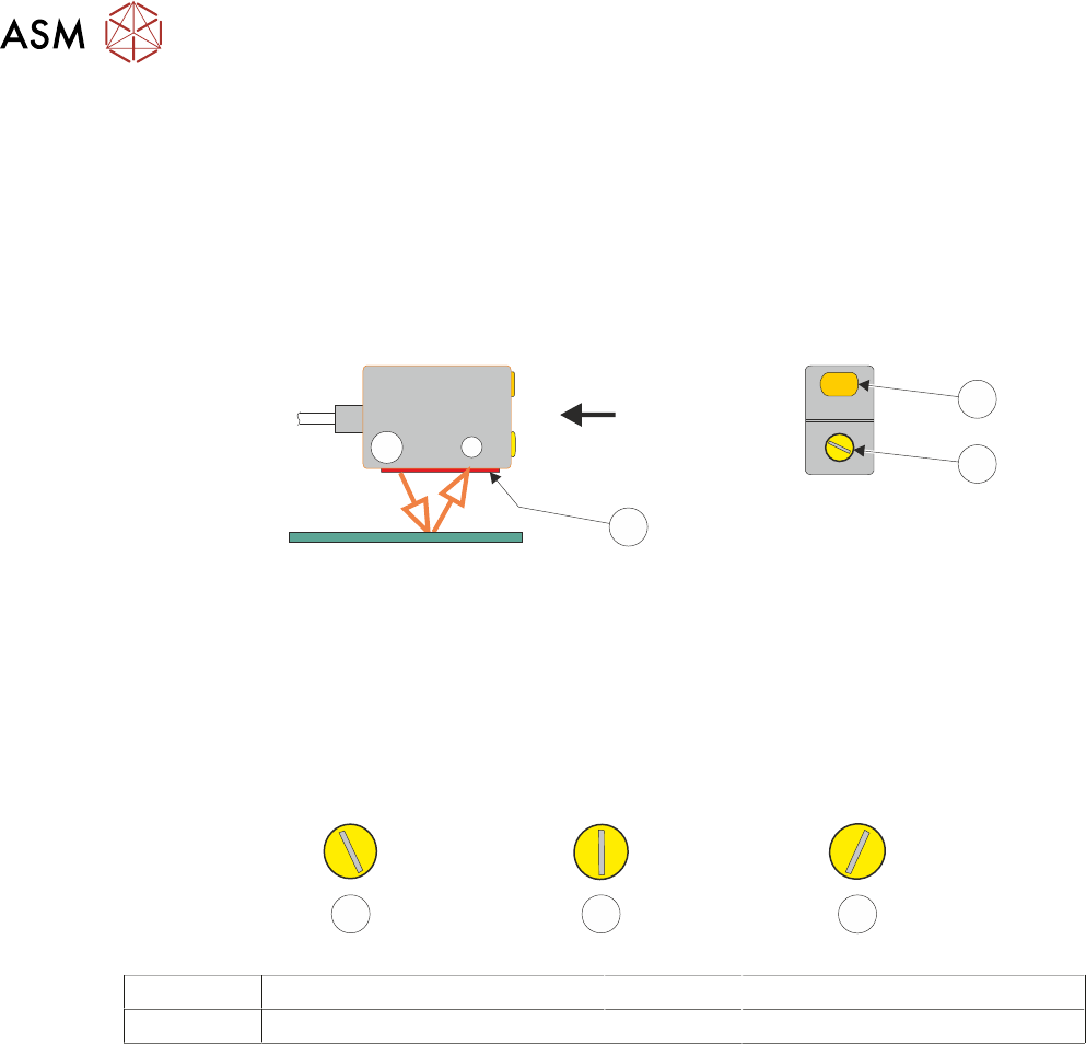
► Position the test board (a 0.2mm board if available) on the rails below the sensor (3).
► If the amber LED (1) on the sensor is illuminated, turn the sensitivity/focal length adjustment
(2) anti-clockwise using a plastic trimmer tool until the LED is OFF (or the LED is flickering).
View on Arrow
3
1
2
► Turn the sensitivity/focal length adjustment (2) very slowly in a clockwise direction until the in-
stant the LED (1) is ON (the LED may flicker before fully illuminating).
► Turn the control (2) in a clockwise direction approximately 10 to 20 degrees beyond the point
at which the LED ON.
NOTE
Turning the control more than 10 to 20 degrees beyond the point at which the LED first illuminated
may cause the sensor to detect the tooling whilst printing using thin boards.
1 2 3
1 LED Not Illuminated 3 Final Set Position
2 LED Illuminated
NOTE
The final set position can be at any angle.
► Remove the test board from the machine.
► Refit the screen.
► Select Back.
► Select Exit.
► Select Confirm.
15 BOARD STOP
15.6 ADJUSTMENTS AND SETTINGS
TECHNICAL REFERENCE MANUAL Vol 1 E By DEK 04/2019 199
15.6.2 Configuring the Remote Board Stop
Configuring the remote board stop should only be carried out when called for in one of the following
procedures:
Procedure Reason for Change
Camera to Remote Board Stop -
LHS Configuration
Change from using the camera mounted board stop
to the remote board stop. The remote board stop is
mounted on the left side of the rising table.
Camera to Remote Board Stop -
RHS Configuration
Change from using the camera mounted board stop
to the remote board stop. The remote board stop is
mounted on the right side of the rising table.
Remote Board Stop -
LHS to RHS Configuration
Change the remote board stop location from the left
to the right side of the rising table.
Remote Board Stop -
RHS to LHS Configuration
Change the remote board stop location from the
right to the left side of the rising table.
Remote Board Stop -
Same Side Configuration
Change the remote board stop position when
switching between products with different board
widths.
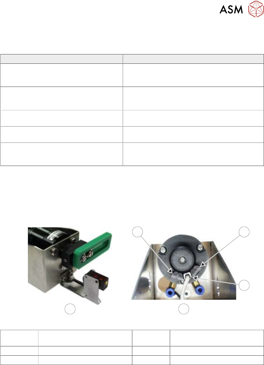
15.6.2.1 LHS Configuration
The remote board stop is configured for the LHS when:
●
The board stop rotates anti-clockwise to the raised position and faces the rear of the machine
when lowered, (as shown below).
●
The reed switch is positioned between the fixed stop and the adjustable stop.
4
1
2
BA
3
A Remote Board Stop
LHS Configured
2 Reed Switch
B View on Rear of Rotary Actuator 3 Fixed Stop
1 Adjustable Stop
15 BOARD STOP
15.6 ADJUSTMENTS AND SETTINGS
200 TECHNICAL REFERENCE MANUAL Vol 1 E By DEK 04/2019
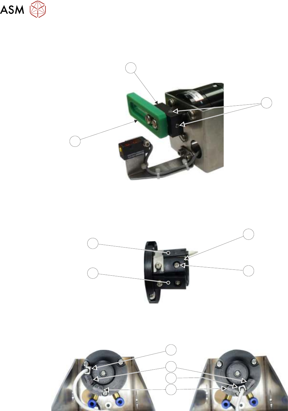
To achieve this carry out the following:
► With the board stop (2) in the position shown below, slacken the two grub screws (1) using a
2mm Allen key.
3
2
1
► Without moving the drive shaft, rotate the rotary arm (3) and board stop (2) 90 degrees clock-
wise, so that the board stop (2) is vertical. Tighten the two grub screws (1).
► Using the access hole in the side of the remote board stop assembly, slacken the adjustable
stop (4) securing screw (5).
4
5
6
7
► Rotate the reed switch (7) and adjustable stop (4) clockwise until the reed switch (7) abuts the
fixed stop (6).
► Tighten the adjustable stop securing screw (5) through the access hole.
RH
LH
Grub Screw
7
4
7
6
► Continue with the appropriate one of the following procedures:
●
15.6.4 "Camera to Remote Board Stop - LHS Configuration" [}206]
●
15.6.7 "Remote Board Stop - RHS to LHS Configuration" [}219]