03217917-01-01E By DEK Technical Reference Manual Vol 1_enPDFA.pdf - 第208页
15 BOARD STOP 15.6 ADJUSTMENTS AND SETTINGS 208 TECHNICAL REFERENCE MANUAL Vol 1 E By DEK 04/2019 15.6.4.3 Fitting the Remote Board Stop ► Fit the remote board stop base clamp locating nut (1) into the attachment slot (2…
15 BOARD STOP
15.6 ADJUSTMENTS AND SETTINGS
TECHNICAL REFERENCE MANUAL Vol 1 E By DEK 04/2019 207
15.6.4.2 External Services
► Select Shut Down.
► Select Continue.
► Switch the mains isolator to OFF.
► Disconnect the quick release mains air connection at the rear the machine.
► Remove the machine rear cover.
► Remove the left hand side safety cover.
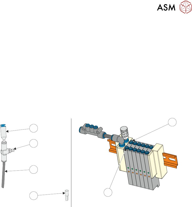
► At the board stop solenoid (16SOL14), on the pneumatic manifold at the rear of the machine:
1. Remove the pipe marked Board Stop from the front port (A) (2).
2. If an in-line flow controller is not already connected to the rear port (B) (1), remove the exist-
ing blanking plug (3) from the rear port (B) (1) and fit the in-line flow controller (5), via the
50mm x 4mm pipe (4) (both supplied with the remote board stop) to the rear port (B) (1). The
in-line flow controller (5) should have a self-seal connector (6) at its open end.
1
2
3
4
5
6
3. Fit the pipe marked Remote/B/Stop Up - LH to the front port (A) (2).
4. Fit the pipe marked Remote/B/Stop Down - LH to the in-line flow controller, self-seal con-
nector (6)fitted to the rear port (B) (1).
► Behind the front cover, mounted on the machine frame:
1. Remove plug BPL6 from socket BSK6.
2. Connect plug BPL6A to socket BSK6.
► Fit the rear cover.
15 BOARD STOP
15.6 ADJUSTMENTS AND SETTINGS
208 TECHNICAL REFERENCE MANUAL Vol 1 E By DEK 04/2019
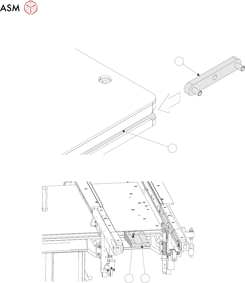
15.6.4.3 Fitting the Remote Board Stop
► Fit the remote board stop base clamp locating nut (1) into the attachment slot (2) on the left
hand side of the rising table.
1
2
► Attach the base clamp (3) to the locating nut (1), in the correct position in the Y axis for the
product, using a 4mm Allen key and M5 securing screw and washer (4).
4
3
► Mark the centre point, in the X axis, on the front of the product board.
► Place the product board on the rails with the board centre point at the Camera Reference Po-
sition (white dot on front rail).
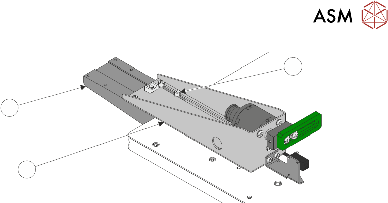
► Before fitting the remote board stop assembly to the base clamp, ensure that the board stop is
configured for left hand side operation, 15.6.2.1 "LHS Configuration" [}199] refers.
► Lay the remote board stop assembly (5) onto the base clamp (6) so that the board stop is
clear of the board.
15 BOARD STOP
15.6 ADJUSTMENTS AND SETTINGS
TECHNICAL REFERENCE MANUAL Vol 1 E By DEK 04/2019 209
7
6
5
► Using the appropriate slots, loosely secure the remote board stop assembly (5) to the base
clamp (6), using the four M5 cap head screws (7).
► Connect plug 8PL05 to socket 8SK05L.
► Connect the pipe marked Remote/B/Stop L1 to the in-line connector on the pipe marked 1 on
the remote board stop.
► Connect the pipe marked Remote/B/Stop L2 to the in-line connector on the pipe marked 2 on
the remote board stop.
► Refit the left hand side safety cover.
► Reconnect the mains air quick release connection to the machine.
► Switch the mains isolator to ON.
► Press the Start button.
► When prompted select Diagnostics.
► When prompted press the System button.
► Carry out 15.6.3 "Setting the Remote Board Stop" [}203].