03217917-01-01E By DEK Technical Reference Manual Vol 1_enPDFA.pdf - 第273页
17 CAMERA SYSTEM MODULE 17.3 ADJUSTMENTS AND SETTINGS TECHNICAL REFERENCE MANUAL Vol 1 E By DEK 04/2019 273 ► Using the Next or Previous button highlight Set Reference Position . ► Select Run Diagnost . The message ‘ Thi…
17 CAMERA SYSTEM MODULE
17.3 ADJUSTMENTS AND SETTINGS
272 TECHNICAL REFERENCE MANUAL Vol 1 E By DEK 04/2019
► Select Run Diagnost. The message ‘This Will Alter The Printer ConfigurationFile - Please
Confirm’ is displayed.
► Select Confirm.
► Using the Next or Previous button highlight Home Rising Table.
► Select Run Diagnost.
► Adjustment Complete - Refit the left hand safety cover.
► Select Exit.
► Select Exit.
► Remove the board from the rails.
► Select Back.
► If the vision height has been adjusted a vision calibration and an offset calibration must be
carried out.
17.3.6 Camera Focus
The camera focus is factory set and sealed and should not need adjustment.
17.3.7 Camera Reference Position
► Select Maintenance.
► Select Diagnostics.
► Using the Next or Previous button highlight Camera Axes.
► Select Select Module.
► Using the Next or Previous button highlight Home Camera X Axis.
► Select Run Diagnost.
► Using the Next or Previous button highlight Home Camera Y Axis.
► Select Run Diagnost.
► Using the Next or Previous button highlight Initialise Vision System.
► Select Run Diagnost.
► Select Drive to Reference Position.
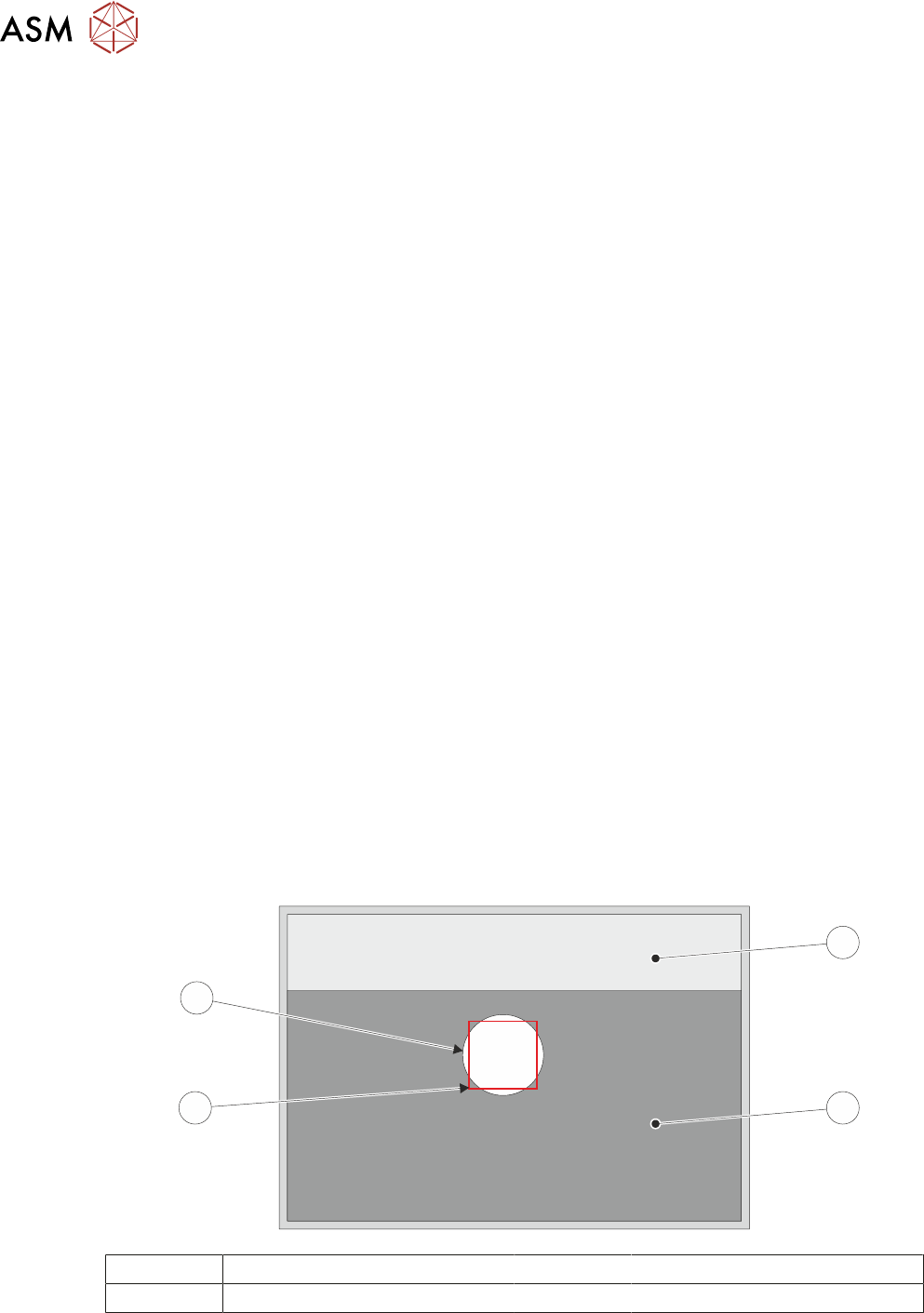
► Select Run Diagnost, a box and the white dot on the board clamp are visible on the monitor.
1
2
3
4
1 Board Clamp Foil 3 Box
2 Board Clamp 4 White Dot
► If the reference position is correct, go to Reference Correct.
► Using Move Camera X Axis Using Jog Buttons and Move Camera Y Axis Using Jog But-
tons, position the box centrally inside the white dot, as shown in the illustration.

17 CAMERA SYSTEM MODULE
17.3 ADJUSTMENTS AND SETTINGS
TECHNICAL REFERENCE MANUAL Vol 1 E By DEK 04/2019 273
► Using the Next or Previous button highlight Set Reference Position.
► Select Run Diagnost. The message ‘This Will Alter The Printer ConfigurationFile - Please
Confirm’ is displayed.
► Select Confirm.
► Reference Correct - Select Exit.
► Select Exit.
► Select Back.

17 CAMERA SYSTEM MODULE
17.4 REPLACEMENT PROCEDURES
274 TECHNICAL REFERENCE MANUAL Vol 1 E By DEK 04/2019
17.4 REPLACEMENT PROCEDURES
17.4.1 Camera
WARNING
BOARD CLAMPS. EXTREME CARE MUST BE EXERCISED WHEN WORKING IN
THE TOOLING AREA OF THE MACHINE TO AVOID INJURY. THE FOILS ON THE
FRONT AND REAR BOARD CLAMPS ARE VERY SHARP.
17.4.1.1 Removal
► Select Open Cover Commands.
► Select Carriage To Rear.
► Select Back.
► Select Shut Down.
► Select Continue.
► Switch the mains isolator to OFF and lockout the isolator.
► Open the printhead cover.
► Remove the stencil.
► To gain access to the camera for removal, move the camera forward and central over the
table by manually moving the camera carriage.
► Remove the following connectors from the rear of the camera unit:
●
10SK17
●
10SK13
► Loosen the two camera mount screws and lift the dovetail fixings to free the camera, lift the
camera out of the camera mount.