03217917-01-01E By DEK Technical Reference Manual Vol 1_enPDFA.pdf - 第58页
5 MACHINE OVERVIEW 5.1 MODULE OVERVIEWS 58 TECHNICAL REFERENCE MANUAL Vol 1 E By DEK 04/2019 5.1.17 Foreign Machine Interface (FMI) Module The FMI provides a communications link between upline/downline machines and the D…
5 MACHINE OVERVIEW
5.1 MODULE OVERVIEWS
TECHNICAL REFERENCE MANUAL Vol 1 E By DEK 04/2019 57
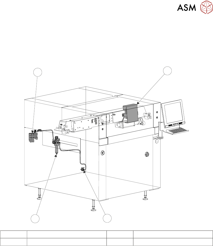
5.1.16 Pneumatics Module
The function of the pneumatics module is to supply regulated air pressure to the pneumatic devices
throughout the machine. The air supply is routed to the required pneumatic device via an electric-
ally operated solenoid valve controlled by the machine control system.
There are two banks of pneumatic solenoids, one located on the rear frame of the machine and the
other located on the print carriage.
1
2
4
3
1 Print Carriage Solenoid Bank 3 Regulator/Filter
2 Pneumatics Input 4 Rear Solenoid Bank
5 MACHINE OVERVIEW
5.1 MODULE OVERVIEWS
58 TECHNICAL REFERENCE MANUAL Vol 1 E By DEK 04/2019
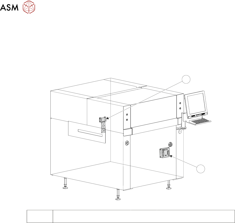
5.1.17 Foreign Machine Interface (FMI) Module
The FMI provides a communications link between upline/downline machines and the DEK
machine.
The FMI pod, fitted to the rear of the machine, is used to communicate with upline/downline ma-
chines using SMEMA, Fuji or Panasonic interfaces.
The Multi-Interface Unit (MIU), fitted inside the front cover of the machine, is used to communicate
with upline/downline machines using all other protocols.
1
2
1 Foreign Machine Interface Pod
(FMI)
2 Multi-Interface Unit (MIU)

5 MACHINE OVERVIEW
5.2 MACHINE PRINT CYCLE
TECHNICAL REFERENCE MANUAL Vol 1 E By DEK 04/2019 59
5.2 MACHINE PRINT CYCLE
The following, is a typical machine print cycle, with camera mounted board stop and squeegees
used as the paste applicator system:
1. Print is selected, the printhead cover lock is engaged and the rising table carries out a rail lif-
ted check.
2. The camera positions itself at the board stop co-ordinates.
3. The print carriage moves to the start of the print stroke and both squeegees drive to their set
dwell height. The chase clamps are energized, clamping the chase in position.
4. The board is transported into the machine stopping at the board stop.
5. The transport belts stop running as soon as the board stop sensor detects the board.
6. The board clamp mechanism operates, clamping the board in position and the board stop re-
tracts.
7. The camera carriage drives to the position determined by Fiducial 1 X and Y co-ordinates.
8. The print carriage is driven to its enhanced start position and the appropriate squeegee is
driven down to start height.
9. The rising table carries out a rail lift check and drives up to vision height.
10. The vision data window displays the board fiducial on the left and the stencil fiducial on the
right of the split display.
11. The fiducials are located and a small blue cross with the fiducial outline appears in the centre
of each fiducial on the split display indicating successful location.
12. While the camera drives to Fiducial 2 X and Y co-ordinates, the location of the Fiducial 1
board and stencil fiducials are copied to the align data structure.
13. Fiducial 2 board and stencil fiducials are located.
14. The chase clamps are de-energised and the screen actuators carry out a rough alignment on
the screen. The chase clamps are re-applied securing the screen.
15. The camera relocates Fiducial 1 and 2. On completion, the camera carriage drives to its home
position.
16. The chase clamps are de-energised and fine alignment on the screen is carried out. On com-
pletion, the chase clamps are re-applied.
17. The relevant squeegee is driven down to make contact with the screen with 0.5kg force.
18. The rising table drives up to the print height.
19. The appropriate squeegee is driven down to the calculated pressure setting, as set in the
board parameter menu.
20. The print carriage drives in the appropriate direction to perform a print stroke.
21. The squeegee mechanism releases full pressure but keeps the squeegee in contact with the
stencil with 0.5kg force (hold height).
22. The rising table is lowered to separation distance at separation speed. Once separation dis-
tance has been reached the rising table accelerates to its normal speed, lowering the table to
transport height. The board clamps are released and the relevant squeegee is raised to dwell
height.
23. The front and rear transport belts drive until the board is detected at the output sensor and the
chase clamps are released.
24. The board count and stencil cleaner cycle counts are incremented. If the stencil cleaner count
has reached the value set by the clean stencil rate, the appropriate cycle is performed.