CP40 service manual.pdf - 第100页
1. Head Part (CP-40) Version Date WA QA CA Note 00 Nov04 O O

1. Head Part
(CP-40)
40_WA Addition
No Classification Material No. Nomenclature Specification
BOM
Qty. Base
1
Device
J1200120 HEXA SUPPORT [M3*5(BOLT-NUT)] M3*5(BOLT-NUT) 6 PC
2
Device
J1300170 SOCKET HEAD SCREW [M3*8] M3*8 6 PC
3
Device
J1300468 SPRING WASHER [M3] M3 6 PC
4
Device
J2101854 P/S PANEL UPPER [0135-614408-P1] 0135-614408-P1 1 PC
5
Device
J6309008A CARD GUIDE [TRCG-3.300] TRCG-3.300 6 PC
6
Device
J7061074B SCM BKT SUPPORT [J7061074A] J7061074A 1 PC
7
Device
J7061075B SCM BOARD HOUSING [J7061075B] J7061075B 1 PC
8
Device
J7061076B SCM BOARD HOLDER [J7061076B] J7061076B 3 PC
9
Device
J9055051A SA SENSOR HEAD [J9055051A] J9055051A 3 PC
10
Device
J9060068A SA SCM BOARD [J9060068A] J9060068A 3 PC
11
Device
J7269005A SA VISION CAP [J7269005A] J7269005A 3 PC
12
Device
J1202055 RS 232 MODULE [JP-OCTAL1232] JP-OCTAL1232 1 PC
13
Device
J1202287 POWER SUPPLY [SA100-BDB] SA100-BDB 1 PC
14
Cable
J9063006B SA SENSOR CABLE [SA-A01] SA-A01 3 PC
15
Cable
J9063007A SA POWER CABLE [SA-A31] SA-A31 3 PC
16
Cable
J9061429A SA 232 CABLE ASS'Y [SA-A61] SA-A61 1 PC
17
Cable
J9063009A SA ENCODER CABLE [SA-A11] SA-A11 3 PC
Version Date WA QA CA Note
00 Nov04 O O
1. Head Part
(CP-40)
Version Date WA QA CA Note
00 Nov04 O O
1. Head Part
(CP-40)
Material Refer to Attached Materials.
S/W MMI INSTALL CD
Tool Cross and Flat-head Screwdrivers(Large, Small), Digital Tester
<Procedures>
1. Commonly Usable Part
a. Bracket Fixing Hole of Quad Aligner and Woori Aligner on the Front Middle Plate
(For Initial Model, WA Fixing Hole may not be Made.)
b. Power Supply of Quad Aligner and Wa Aligner
c. For CP40CV Equipment, CE is not Added Newly and there is no Additional Items to Wago Terminal.
(Only WA is Attached to CA Equipment and CE Part is not Changed.)
2. Part to be Changed (Equipment Modification Method)
a. Remove the Material Shown in 40_QA Removal of this Document from the Equipment(14 Sorts).
(Part to be Excepted from CP40LV Equipment)
b. Prepare to Attach the Material Shown in 40_WA Addition of this Document to Equipment(14 Sorts)
.
(Material to be Added to CP40LV Equipment)
3. Working Method
a. Remove Quad Aligner Cable of Cableveyor and Attach WA Aligner Cable.
b. Remove Quad Aligner Board from Equipment and Remove Bracket and Cable.
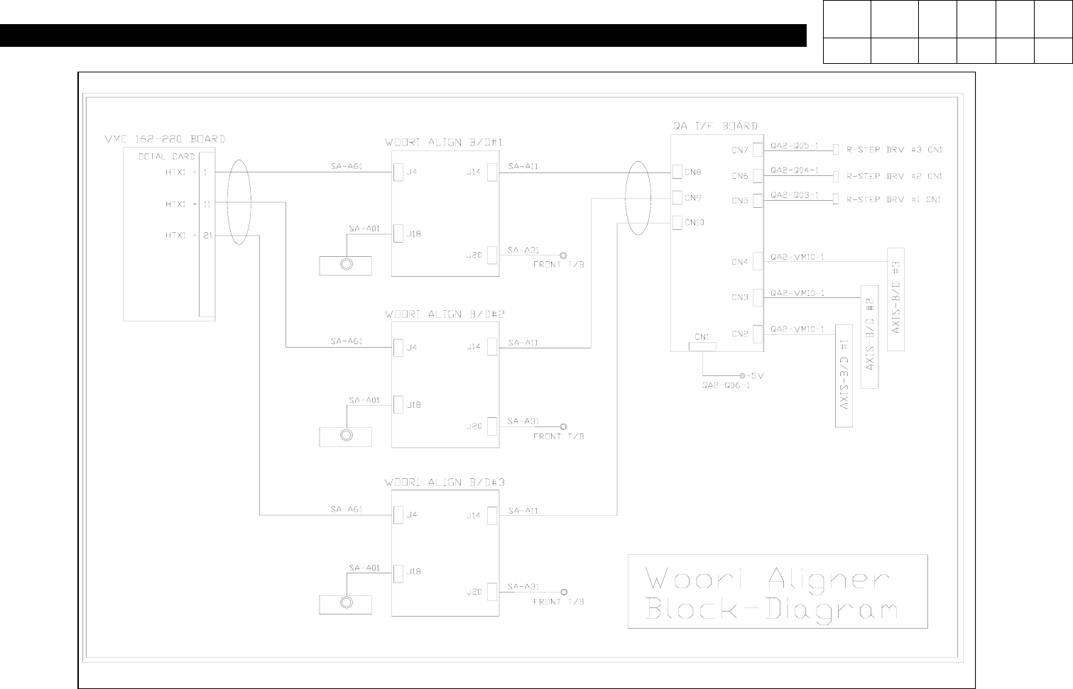
c. Attach WA Bracket, Attach Wa Board and Connect Wire (
Wa Aligner Wiring Block Diagram
).
4. MMI Installation
5. Profile Setting
- Refer to Line Profile Optimization Setting Method for SI(20030711T)CP-204050.
Version Date WA QA CA Note
00 Nov04 O O
1-3-8. QA => WA Change
1. Preparation