CP40 service manual.pdf - 第123页
3. X-Y PART (CP-40) 3. Secure M5*20 Hexagon Wrench Bolts. 4. While Moving Head from Side to Side, Check Gage. 5. Using Loctite, Perform Bonding of Fo ur M5*20 Bolts and T wo M4*20 Bolts. M5*20 Hexagon Wrench Bolt * 4ea M…
3. X-Y PART
(CP-40)
2.
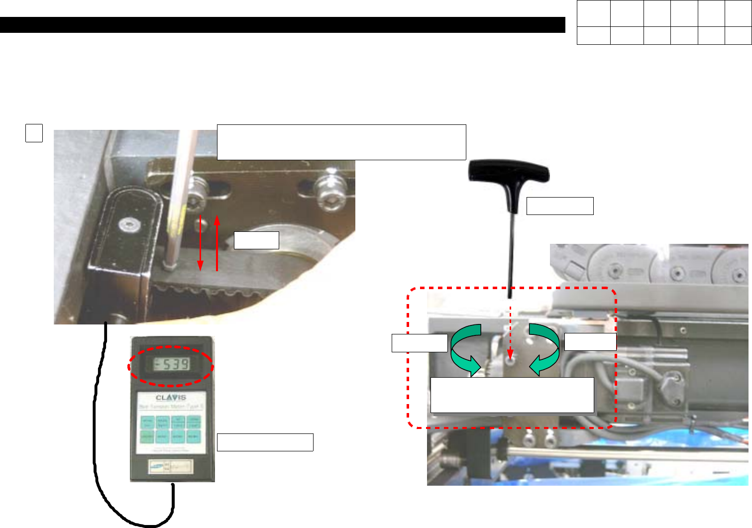
WhileTurningTwoM4*20HexagonWrench Bolts and Tapping them, Adjust Level Value of Tension Gage to 184 +- 20.
Caution) Turing Clockwise Strengthens Tension while Turning Counterclockwise Weakens Tension.
Tension Gage
L-Wrench
(Using Other Wrench will Do no Harm)
Belt
2
M4*20 Hexagon Wrench
Bolt*2EA
Decrease
Increase
T-Wrench
=> Adjust Level Value of
Tension Gage to184 +- 20.
Version Date WA QA CA Note
00 Nov04 O O O
3. X-Y PART
(CP-40)
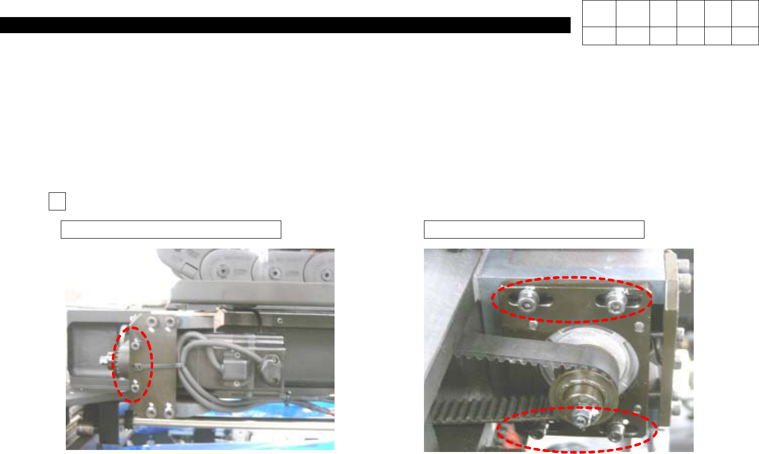
3. Secure M5*20 Hexagon Wrench Bolts.
4. While Moving Head from Side to Side, Check Gage.
5. Using Loctite, Perform Bonding of Four M5*20 Bolts and Two M4*20 Bolts.
M5*20 Hexagon Wrench Bolt * 4eaM4*20 Hexagon Wrench Bolt * 2ea
5
Version Date WA QA CA Note
00 Nov04 O O O
3. X-Y PART
(CP-40)
3-3-4.
X&Y Axis +,- Limit Measurement
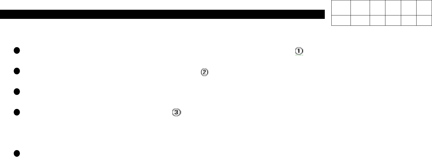
In
Setup,
Select Input Password and Input
SCP
in Enter Password Window
(Display )
.
System Setup Window is Displayed as Follows
(Display )
.
In System Setup Window, Select
Position
and then
System Limit
.
In Limit Position Window, Select
Auto(Display )
.
=> After S/W Limit is Measured Automatically, the Measured Value will be Displayed.
Click OK to Finish.
Version Date WA QA CA Note
00 Nov04 O O O