CP40 service manual.pdf - 第91页
1. Head Part (CP-40) <Assembly> 1. Move Head to Fr ont F eeder Base and Secure Two Bolts and a Filter on the Front of Cover. 2. Move Head to Rear Feeder Base and Secure the Rest Two Bolts. Version Date WA QA CA Not…
1. Head Part
(CP-40)
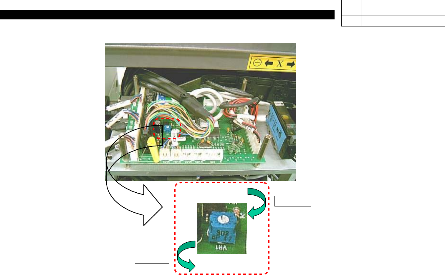
5. Adjust VR1 on I/F Board Until the Value is Over 560 [mmHg].
# Clockwise : Decrease Vacuum Level
Counterclockwise : Increase Vacuum Level
Decrease
Increase
Head I/F Board Ass'y
Version Date WA QA CA Note
00 Nov04 O O O

1. Head Part
(CP-40)
<Assembly>
1. Move Head to Front Feeder Base and Secure Two Bolts and a Filter on the Front of Cover.
2. Move Head to Rear Feeder Base and Secure the Rest Two Bolts.
Version Date WA QA CA Note
00 Nov04 O O O
1. Head Part
(CP-40)
Version Date WA QA CA Note
00 Nov04 O O O
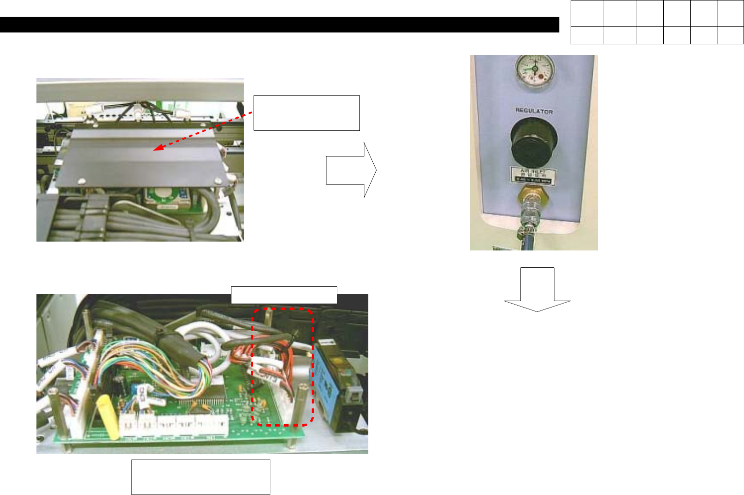
1. Move Head to the Rear Acryl Cover.
2. Put Off Power
Switch.
3. Remove Air.
4. Disconnect Four Bolts from the Upper Cover of Head I/F
Board.
5. Disconnect Head CN11~13(Solenoid Cable) and
CN14~16(Generator Cable).
CN11~CN16
HEAD I/F BOARD
J9800392
Head I/F Cover
J7152011B
1-3-5. Vacuum Generator Replacement