CP40 service manual.pdf - 第147页
4. Feeder Base & ANC (CP-40) 1) Using Teaching Box, Move Head to the Rear. 2) Turning Conveyor Width Adjusting Handle t o Left-hand to Widen the Conveyor Width as Wide as Possible. 3) Loosen Seven M3*6 Toras Bolts to…
4. Feeder Base & ANC
(CP-40)
Origin Fixture is Required to Set Feeder Base Parallelism, but in the Field, Feeder can also be Used.
Feeder Base Parallelism is
Front/Rear SPEC : +- 0.1
.
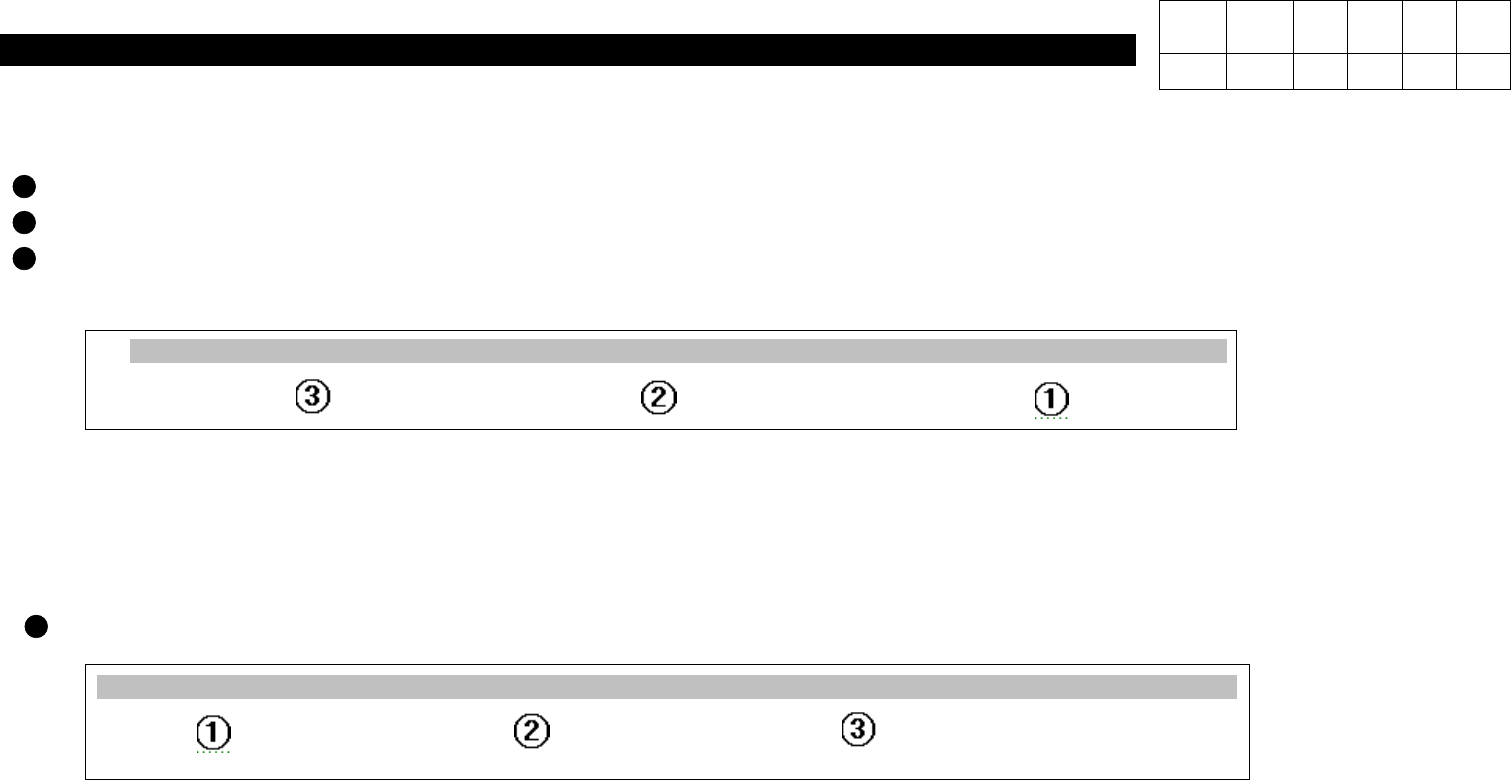
For the Front, Set the Parallelism according to the below Figure.
=>
As shown in the above Figure, Put Feeder on Feeder Base in Order of
No.52=> No.27=> No.13
and Perform Setting
until the Value is within
SPEC : 0.1
.
For the Rear, Set the Parallelism according to the below Figure.
=>
As shown in the above Figure, Put Feeder on Feeder Base in Order of
No.52=> No.27=> No.13
and Perform Setting
until the Value is within
SPEC : +- 0.1
.
1 2 ------ 12
13
14 15 -------------- 24 25 26
27
28 29 ------------- 48 49 50 51
52
52
51 50 49 48 ---------- 30 29 28
27
26 25 --------------- 15 14
13
12 ------ 3 2 1
Version Date WA QA CA Note
00 Nov04 O O O
4-3-6. Feeder Base Parallelism Setting
4. Feeder Base & ANC
(CP-40)
1) Using Teaching Box, Move Head to the Rear.
2) Turning Conveyor Width Adjusting Handle to Left-hand to Widen the Conveyor Width as
Wide as Possible.
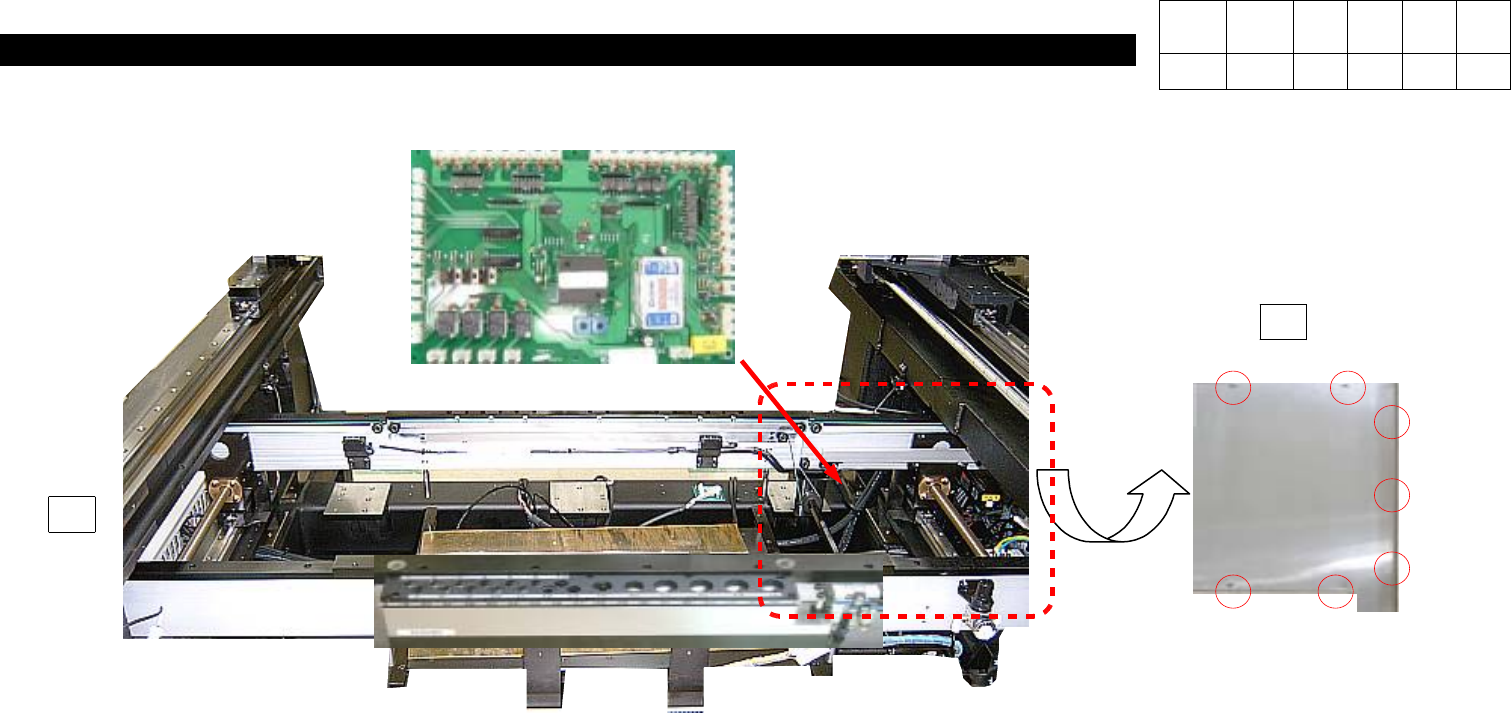
3) Loosen Seven M3*6 Toras Bolts to Open Chip Cover on the Left-hand inside Equipment.
4) Disconnect Connector on PCB.
5) Loosen Six Spherical Head Bolts to Disconnect Feeder I/F Board.
6) Replace New PCB and Assemble it according to Reverse Procedures.
J9800393
Conveyor I/F Board Ass'y
J2102038
Chip Cover Side 2
3
2
Version Date WA QA CA Note
00 Nov04 O O O
4-3-7. Conveyor I/F Board Replacement
4. Feeder Base & ANC
(CP-40)
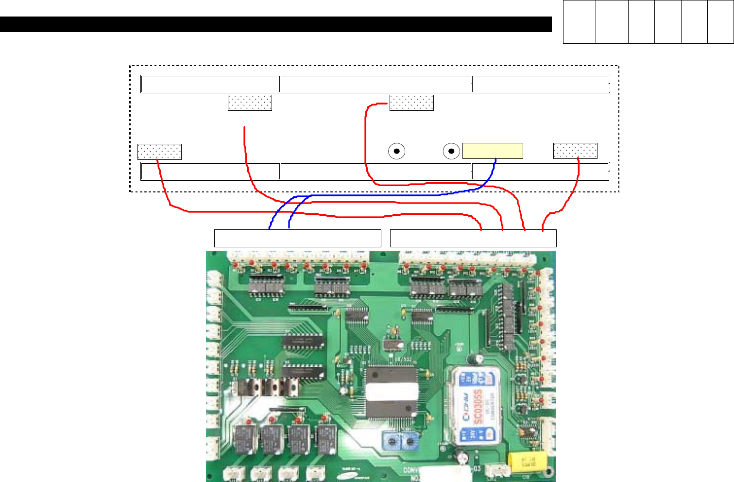
INPUT SENSOR
PLACE STOPPER
HOLE
FIXER
OUTPUT SENSOR
PLACE SENSOR
WAIT SENSOR
17 18 19 20 21 22 23 24 25 26 27 28 29 30 31 32
J9800393
Conveyor I/F Board Ass'y
19 Up
20 Down
J3212025A
SENSOR (Former J1301569)
CN29 CV17-1
CN30 CV18-1
CN31 CV19-1
CN32 CV20-1
Version Date WA QA CA Note
00 Nov04 O O O
4-3-8. Conveyor I/F Board Cable Check