CP40 service manual.pdf - 第152页
5. Electric Device (CP-40) 5-1. Trouble Diagnosis Guide Table Malfunction Trans Former Power Supply Op Panel Circuit Protec t CP Re placement 4 Power Supply Replacement 5 OP Panel SW Replacement 4 OP P anel SW Soldering …
4. Feeder Base & ANC
(CP-40)
8)Flow PCB to Check Proper Operation of Each Sensor.
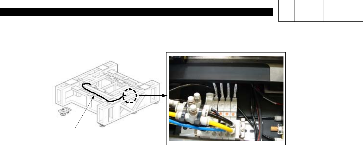
7)Extend Pneumatic Air Hose to Place Stopper(Replace Newly) -.Refer to Fig. 4.
#The Second Hose form the Right Among Air Blocks is for Place Stopper.
<Fig. 4> Place Stopper Pneumatic Line
AIR HOSE
AIR BLOCK
Version Date WA QA CA Note
00 Nov04 O O O
5. Electric Device
(CP-40)
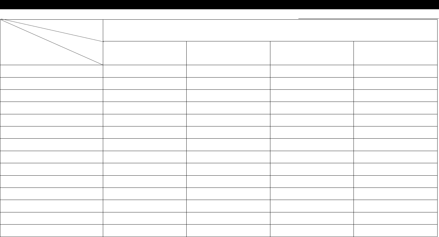
5-1. Trouble Diagnosis Guide Table
Malfunction
Trans Former Power Supply Op Panel Circuit Protect
CP Replacement 4
Power Supply Replacement 5
OP Panel SW Replacement 4
OP Panel SW Soldering Check 3
Lamp Replacement 3 5
Power Supply Cable Check
2
\
5
AC/DC Line Check 3 2 2 4
Cable Disconnection Check 4 1 3
Power Supply 24V Output Check 1
Main Power Input/output Check 1 1
Circuit Break Check 2
Parts
Symptom
Check and Action
# Number Indicates Priority of Check Items.
5. Electric Device
(CP-40)
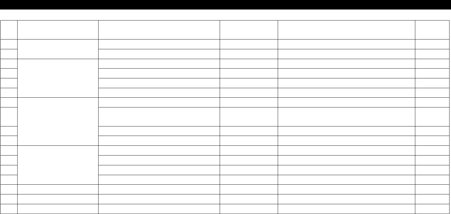
NO Symptom Possible Cause Error Code Action
Instructio
n
1
Transformer Malfunction
Input Voltage is Low. Connect Disconnected Cable. 5-3-1
2 Noise Tighten Main Power Connector Bolts. 5-3-1
3
Power Supply
24V is not Output. Connect Disconnected 24VG and 24VP. 5-3-2
4 Bad Stick Feeder 24V AC/DC Lining 5-3-2
5 Front AC Power Malfunction Disconnect Cable. 5-3-2
6 When Checking I/O, 24V is Down. Modify CV CN 37 Pin. 2-3-2
7
OP Panel
Reset SW Always Remains ON. Replace Reset SW. 5-3-3
8
Functions of OP Panel SWs are
Exchanged.
Modify Soldering. 5-3-3
9 Ready SW Color is not Correct. Replace Lamp.
10 Main Panel SW Malfunction Modify Wiring.
11
Circuit Protect
Stick Feeder Malfunction Check and Replace CR9. 5-3-2
12 Servo Driver Malfunction Check and Replace Circuit Protect. 5-3-2
13 PC Malfunction Check and Replace CP1. 5-3-2
14 Step Driver Malfunction Check and Replace CR2-1. 5-3-2
15
16
17
5-2. Trouble Diagnosis