CP40 service manual.pdf - 第56页
MODULE ERROR CODE Symptom and Cause ACTION Service Manual Woori Align Part $89C2 Aligner inspected bad y dimension[28] (Head 2) Y size of part measured by Aligner exceeds the tolerance of size Y registered. This occurs c…
MODULE
ERROR
CODE
Symptom and Cause ACTION
Service
Manual
$715, 0,
"[Part] ", "Cycle=%d Head=%d "
Air pressure shutdown delay time is incorrect.
Air pressure shutdown Delay time shall be -1000~1000ms.
$716, 0,
"[Part] ", "Cycle=%d Head=%d "
Air pressure discharge delay time is incorrect.
Air pressure discharge time shall be 0~1000ms.
$718, 0,
"[Part] ", "Cycle=%d Head=%d "
Dump Delay time is incorrect.
Dump time shall be 0~10000ms.
$719, 0,
"[Part] ", "Cycle=%d Head=%d "
Air pressure shutdown delay time in Dump is incorrect.
Air pressure shutdown time when Dump shall be -1000~1000ms.
$720, 0,
"[Part] ", "Cycle=%d Head=%d "
Air pressure discharge delay time in Dump is incorrect.
Air pressure discharge delay time when Dump shall be 0~1000ms.
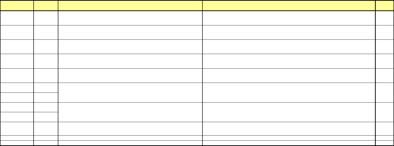
$800,
$803, 0,
$1800,
$1801, 0,
$1802, 0,
"[Dump-box] ", "No.=%d Head=%d "
Dump position Y value of Dump Box is incorrect.
Dump position Y shall be in system area.
"[Dump-box] ", "No.=%d Head=%d "
Dump position X value of Dump Box is incorrect.
Dump position X shall be in system area.
"[Dump Box] ", "No.=%d "
Dump height Z of Dump Box is incorrect.
Dump height Z shall be -3 ~ 15mm.
- 43 -
MODULE
ERROR
CODE
Symptom and Cause ACTION
Service
Manual
Woori Align
Part
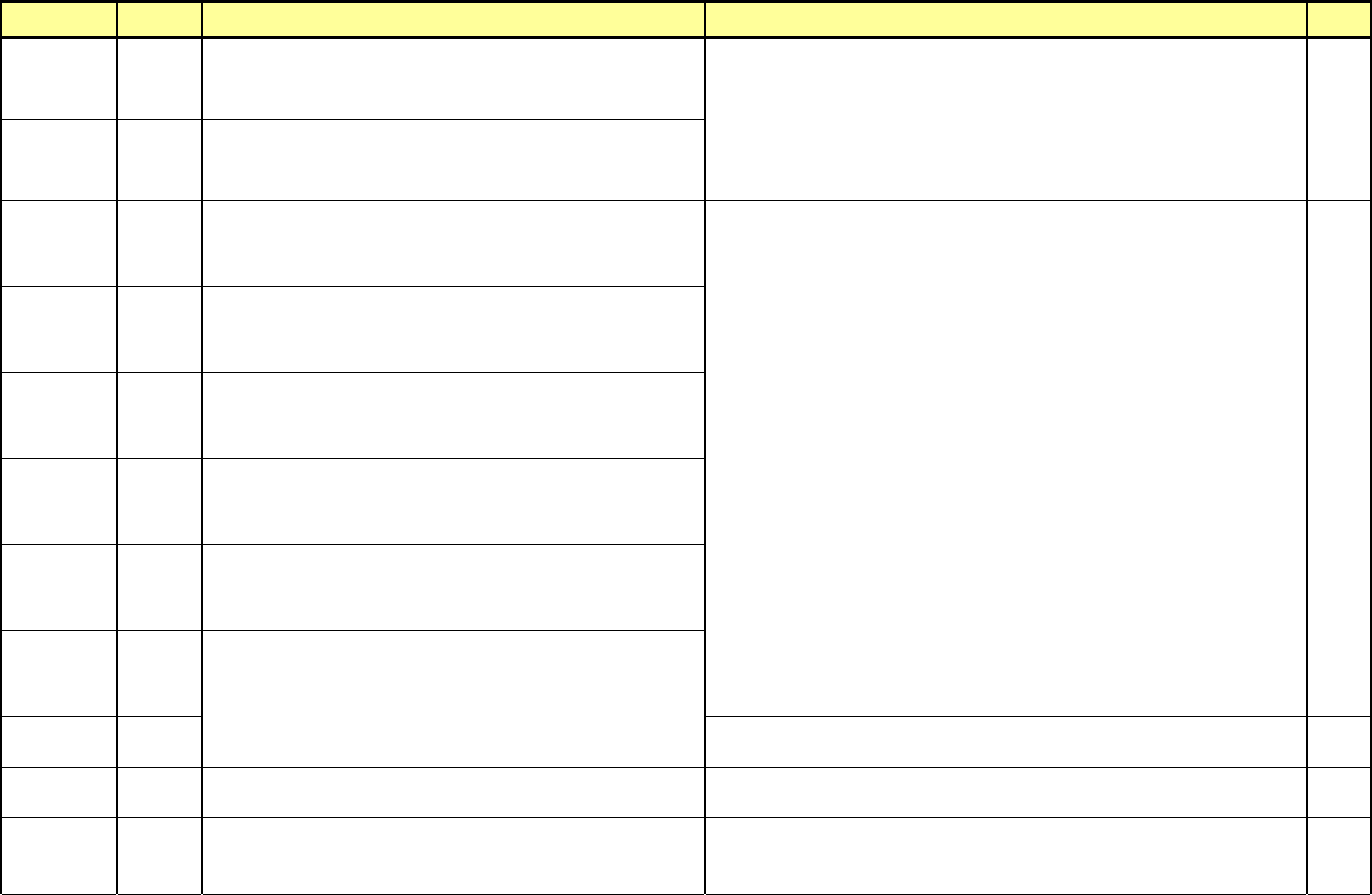
$89C2
Aligner inspected bad y dimension[28] (Head 2)
Y size of part measured by Aligner exceeds the tolerance of size Y registered. This
occurs caused by pickup(tombstome) with part upwards, failure of part pickup,
incorrectly inputted scan size of part, or incorrect align height of part.
12-3-1
12-3-3
12-3-7
12-3-8
$89C3
Aligner inspected bad y dimension[28] (Head 3)
Y size of part measured by Aligner exceeds the tolerance of size Y registered. This
occurs caused by pickup(tombstome) with part upwards, failure of part pickup,
incorrectly inputted scan size of part, or incorrect align height of part.
12-3-1
12-3-3
12-3-7
12-3-8
$89D1
Aligner inspected low x quality[29] (Head 1)
X score of part measured is too low(less than 80 scores). This occurs caused by
slip of part during align.(Rotation of part exceeds degree of 15.)
$89D2
Aligner inspected low x quality[29] (Head 2)
X score of part measured is too low(less than 80 scores). This occurs caused by
slip of part during align.(Rotation of part exceeds degree of 15.)
12-3-1
$89D3
Aligner inspected low x quality[29] (Head 3)
X score of part measured is too low(less than 80 scores). This occurs caused by
slip of part during align.(Rotation of part exceeds degree of 15.)
12-3-3
$89E1
Aligner inspected low y quality[30] (Head 1)
Y score of part measured is too low(less than 80 scores). This occurs caused by
slip of part during align.(Rotation of part exceeds degree of 15.)
12-3-7
$89E2
Aligner inspected low y quality[30] (Head 2)
Y score of part measured is too low(less than 80 scores). This occurs caused by
slip of part during align.(Rotation of part exceeds degree of 15.)
12-3-8
$89E3
Aligner inspected low y quality[30] (Head 3)
Y score of part measured is too low(less than 80 scores). This occurs caused by
slip of part during align.(Rotation of part exceeds degree of 15.)
Vision Part $AA00
Vision Fiducial Data Ready Error
Occurs when data not inputted exists in Fiducial Data exists or error occurs.
Check that Fiducial Data in use is inputted correctly, and if not inputted, input the data correctly.
$AA01
Vision Fiducial Acquisition Error
Occurs when grab is not possible when grabbing the Vision Fiducial image.
Check the Vision H/W Type. (Cognex, SSA)
Check the linked condition of Camera Cable.
7-3-1
$AA02
Vision Fiducial Inspection Error
Occurs when it fails to find out Fiducial Mark concerned when Vision Fiducial
Inspection.
Modify correctly the Vision Fiducial Mark Data concerned.
Check that scan size of part registered is identical to that of real part.
Check that Align height of part is proper.
Check that thickness of part registered is identical to that of real part.
Check that tolerance of part is suitable.
Check that picked up condition of part and value of Z-axis inputted are suitable.
Check for feeding condition of Feeder.
Check a Nozzle for abnormal conditions.
Adjust an Align speed.
Check for feeding conditions of Feeder.
- 20 -

0. Install & Driver
(CP-40)
Version Date WA QA CA Note
00 Nov04 O O O
Contents
1.Installation & Test Process
2.Work Base and Check
2.1 Request of Installation and Test
2.2 Copy of Contract Document
2.3 Supplying Specification
2.4 Order Entry Sheet
2.5 Sketch Map of Customer
3.Installation & Test Procedure
3.1 Warehousing Procedure
3.2 Equipment Carrying-in and Setting
3.3 Utility Check and Connection(Air,Electricity,Ground)
3.4 Interface Connection
3.5 Equipment Parameter Inspection and Diagnosis
3.6 Safety Device Check and Safety Education
3.7 Warming Up and Start